Map View Tools: Cross Section Display Controls
 The Map View Cross Section Display Controls dialog box is used to select existing cross sections to display in the Map View window, adjust the display parameters of the sections, and adjust the dynamic cross section controls. You can also save, load, delete, copy and create cross sections from this dialog box.
To open the Map View Cross Section Display Controls dialog box, on the Buttons toolbar click  , or from the Edit menu select Cross Section.
Cross Section Controls
The cross section controls at the top of the dialog box are used to turn cross sections on, adjust their display properties, and access the Edit Cross Section dialog box.
Show: Place a check mark next to each cross section you want to display. Cross sections are drawn as a line using the cross section color.
Label: Display a label at each end of the section.
Thick: Use a think link to draw the section on the map.
Edit: Open the Edit Cross Section dialog box to change the name or color of the cross section, or to change the node locations and wells currently associated with the cross section.
Source: The source of the section. This is for information and can't be edited.
Symbol Annotation at Node Points
Size: Specify the size of the symbols drawn at the node points of the cross section.
Increment: Enter an increment for the symbols drawn at the node points of the cross section. A symbol will be placed at each end, and then at every increment.
Dynamic Controls
The Dynamic Controls are applied in all three data views, and control the amount a cross section steps or rotates when using the dynamic control keyboard shortcuts. As you move your section, the original wells will continue to be included in the section if they can be projected perpendicularly. Additional wells are projected when the Projection Buffer is turned on, as long as they fall within the Projection Distance. The Dynamic Controls are available from the Map View Cross Section Display Controls dialog box in the Map View window, and the Select Cross Section dialog box in the Cross Section View window.
Move Step: The distance in meters the section will move when a keyboard shortcut is used.
| Up Arrow | Move section north by the Move Step distance |
| Down Arrow | Move section south by the Move Step distance |
| Left Arrow | Move section east by the Move Step distance |
| Right Arrow | Move section west by the Move Step distance |
Angle: The angle in degrees the section will rotate around the center point when a keyboard shortcut is used.
| Page Up | Rotate section clockwise by the Angle |
| Page Down | Rotate section counterclockwise by the Angle |
Projection Buffer: When this is turned on, the Projection Distance is used to determine which wells are projected onto the cross section. Select where the buffer is measured from the pull down list: On TD, On KB or On Path.
Projection Distance: Enter a projection distance in the units shown, and determine from where the measurement is taken.
On TD: The distance is measured from the bottom hole location to the cross section location.
On KB: The distance is measured from the KB location to the cross section location.
On Path: The distance is measured along the well path.
 Reset Xsect:Reset the position and orientation of the displayed cross section. You can reset the section directly from the main window by clicking
  on the Buttons toolbar.
Other Options
Use the buttons at the bottom of the dialog box to save, load, delete, and copy the section.
 Save: Save the selected cross section to a file.
 Load: Load a cross section file (*.xsec) into your project.
 Delete: Delete the selected cross section. This will permanently remove the section from your project.
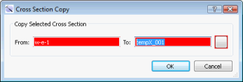
 Copy: Open the Cross Section Copy dialog box. Enter a name for the new cross section, and then click on the color field to open the Color Table and change the cross section line color.
 Create: Open the Define New Cross Section dialog box and graphically create a new cross section on the map.
— MORE INFORMATION

|
Copyright © 2020 | SeisWare International Inc. | All rights reserved |