Template Builder: Template Properties
The Template Properties dialog box is used to design the well bores for the layer currently selected in the Layer Properties dialog box. As you define the template properties the template is updated in 3D space in the display widnow. Changes to the template are saved automatically. Note: Changes to the template are not reflected in the stamped pad of your field plan. You will need to make changes to stamped pad from the Object Properties dialog box in the Pad Plan 2D or Pad Plan 3D windows, or using using the Edit tools in the Pad Plan 2D window.
Layer Properties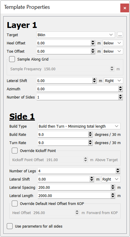
Target: Select a target from the list. Click  to open the Target Properties dialog box to define a new target or edit the properties of the target, including the reference grid, restricting polygons, and color.
Heel Offset: Enter an offset distance in project units between the heel of the well and the grid associated with the target. The offset can applied Above or Below the grid.
Toe Offset: Enter an offset distance in project units between the toe of the well and the grid associated with the target. The offset can applied Above or Below the grid.
Sample Along Grid: Starting from the heel, place an node along the well bore at the specified Sample Frequency. These nodes can be used to edit the well bore and are included in the exported well pad plan.
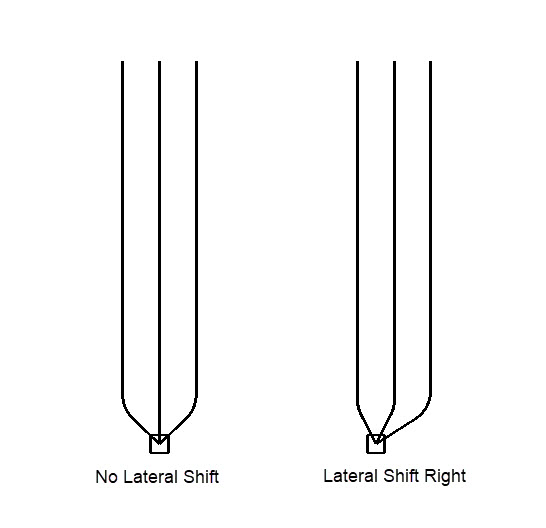
Lateral Shift: Enter a lateral shift of the heel from the platform in project units. The lateral shift can move the well bores to the Right or Left of the vertical section.
Azimuth: Enter the azimuth of the Side 1 well bores in degrees. When you have multiple sides, by default the sides are oriented equally around the vertical section. Change the Offset Azimuth value to change the azimuth of additional sides. Note: The Azimuth Reference is specified when you create a new field plan.
Number of Sides: Specify the number of sides. As you increase this value, additional properties fields are added below the Side 1 properties.
Side Properties
Build Type: Select a build type to determine the trajectory of the well bores.
Build and Turn: Complete the build section and turn section of the well concurrently. The heel point is offset from the main bore at a distance that is the larger value between the radius value of the build or turn rates.
Build then Turn- Minimizing total length: Complete the build section of the well at a constant build rate until the desired depth is reached before starting the turn section. This option minimizes the total length by optimizing the azimuth of the build section before turning.
Build then Turn- Maximizing lateral section: Complete the build section of the well at a constant build rate until the desired depth is reached before starting the turn section. This option maximizes lateral lengths in the formation by always kicking off perpendicularly to the lateral for legs outside the radius of curvature.
Build Rate: Specify the build rate in project units.
Turn Rate: Specify the turn rate in project units.
Override Kickoff Point: Option to move the kickoff point a certain distance above the target.
Number of Legs: Specify the number of legs on the side of the well.
Lateral Shift: Enter a lateral shift in project units for all of legs on the side of the well. The lateral shift can move the well bores to the Right or Left of the vertical section.
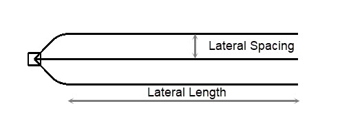
Lateral Spacing: Enter a lateral spacing value in project units to determine the distance between the legs of the well.
Lateral Length: Enter a lateral length from the heel to the toe of the well in project units for the legs of the well. For for templates with multiple legs the lateral length will often be exact at the outer legs, and the inner legs will be extended to allow the legs to align. Wells may not achieve this lateral length when clipping is enabled.
Override Heel Offset from KOP: Option to move the heel point a certain distance away from the kick off point (KOP). A negative value will move the heel point behind the kick off point. Note: The default number shown is the calculated offset based on your settings. Changing this value to be smaller than the default may result in back-building.
Offset Azimuth: Enter the azimuth of the of the well bores in degrees. Side 1 will use the Azimuth value set in the Layer Properties. Note: The Azimuth Reference is specified when you create a new field plan.
Use parameters for all sides: When a template has multiple sides, turn this on to use the same Build Rate, Turn Rate, Number of Legs, Lateral Spacing, and Lateral Length values for all sides. You will still be required to edit Lateral Shift and Offset Azimuth values.
— MORE INFORMATION

|
Copyright © 2020 | SeisWare International Inc. | All rights reserved |