Import Locations
The Import Locations dialog allows the user to import positional data into SeisWare. Data can be imported into SeisWare as raw SEG-P data, or imported into existing SEG-Y files to correct missing positional information.
-
Select the Input Files file using the
 button.
 -
Set the Type of Input Files. If you are using an ASCII file, define the columns.
-
(Optional) Restrict the lines that the SEG-P will be imported onto. By default, all information is imported from the file.
-
Adjust the Coordinate Parameters. For most standard files these can be left at their default values.
-
Click
 to Import.
Note:
Using the standard
format files, the
default settings should import matching line names and shots from the
input file with the line name and shot range for the loaded SEG-Y
existing in SeisWare. If these do not match, nothing will be imported.
If you have no SEG-Y, you can import the SEG-P/UKOOA to "Database Only"
to show where the line exists on the map. If the file is not in a
standard format, use the 2D Columnar ASCII import option.
General Information
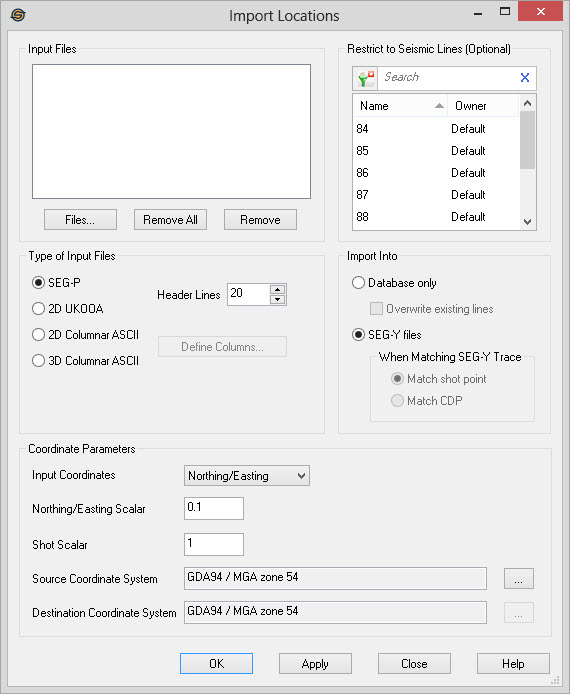
Input Files
Use this area to specify files for import.
Files...: Open a file
browser to select
files.
 Remove All: Remove all
files from the list
of files.
Remove All: Remove all
files from the list
of files.
 Remove: Remove selected
files from the list
of files.
Remove: Remove selected
files from the list
of files.
Type of Input Files
This area allows you to select the type of input file you have.
SEG-P: Input files are standard SEG-P files.
2D UKOOA: Input files are standard 2D UKOOA P1/90 format files.
Header Lines: This allows you to specify how many header lines are in the SEG-P or UKOOA file. It is not used for Columnar ASCII files. The SEG-P standard says there should be 20 header lines in a SEG-P file, but many SEG-P files don't conform, so you may need to override this value. UKOOA files in particular frequently have only 3 header lines, which could result in truncated data if not set correctly.
2D Columnar ASCII: Input files are columnar ASCII files. You define the columns by clicking on the Define Columns... button and selecting the columns to define. For more help with this step refer to the defining columns help file.
3D Columnar ASCII: Input files are columnar ASCII files representing data for 3D surveys. Only three corners of a survey need to be defined in order to import the survey information.
 Define Columns:
Define the columns when
importing ASCII files.
Define Columns:
Define the columns when
importing ASCII files.
Import Into
This area allows you to select how you want to import the files.
Database only: Selecting this option imports the raw SEG-P files into SeisWare. The lines are displayed on the map and can have horizons added to them. Note: You can only perform 3D survey imports using the "Database only" option of the Import Into section.
Overwrite existing lines: This option is only available when importing SEG-P into the database only. If checked any new SEG-P information will overwrite an existing SEG-P line. If unchecked, existing lines are retained. Existing SEG-Y files are never overwritten with SEG-P lines when just importing into the database.
SEG-Y
files: This option imports the
positional information into existing SEG-Y files. Use this when the
SEG-Y files do not already have positional information defined in the
headers.
When Matching SEG-Y
Trace: This area allows you
to specify how to import the
positional information. It is only available when importing Columnar
ASCII files.
Match shotpoint: This option determines which trace to assign positional information to by shotpoint number. Shot must be defined as one of the columns.
Match
CDP: This option
determines which trace to assign positional information to by CDP
number. CDP
must be defined as one of the columns.
This option is most useful when importing Chevron style lines which
have duplicate shotpoints.
Restrict to Seismic Lines
Select the seismic lines that you want the location information imported to. If no lines are selected then the application will attempt to import the all of the locations within the import file into the project. This option is only available when importing data into SEG-Y files.
Left click to select a seismic line, left click and press the Ctrl key on your keyboard to
select multiple seismic lines, or select a group of lines from the
Basemap. To help you make your seismic line selections, you can sort
any of the columns, you can
apply a filter (![]() ),
or you can type a search string into the search
bar to limit the list.
),
or you can type a search string into the search
bar to limit the list.
For additional selection and navigation options right click on the
seismic fileslist to access
the shortcut
menu.
Coordinate Parameters
This area allows you to specify information about the coordinates contained within the file.
Input Coordinates: This option allows you to import positional data from either the northing/easting columns of the SEG-P file or the Latitude and Longitude columns of the SEG-P file. When importing latitude/longitude data it is converted to positional data using either the project's coordinate system, or the source and destination coordinate systems supplied in the dialog.
Northing/Easting
Scalar:
Applies a scalar to the northing/easting values to
convert
them to the units of the destination coordinate system. Typically
SEG-P UTM values are in decimeters, so the default scalar of 0.1
converts them to Meters. For columnar data you will often set this
value to 1.
Shot Scalar: Applies a scalar to shotpoint
values. Often shotpoints found
in
files have been multiplied by 10. Set to 0.1 to return the shotpoint
to it's original value.
Source Coordinate System:This is the coordinate system of
the input SEG-P files. Select
a
coordinate system by clicking on the "..." button. By
default this is set to the coordinate system in the Project Propertiesdialog. If you have
obtained SEG-P files with a
different coordinate system from that of your project (such as a
neighboring UTM zone) you can set this value to automatically convert
the files to the project's coordinate system. If you do not
have a coordinate system defined for the project this area will
initially be blank. If you are importing northing/easting values the
coordinate system does not need to be set.
Destination Coordinate System: This is the
destination coordinate system for the project.
Select
a coordinate system by clicking on the "..." button. By
default this is set to the coordinate system in the Project Properties dialog. It is best to
set this in the project
properties rather than in this dialog. If you do not have a
coordinate system defined for the project this area will initially be
blank. If you are importing northing/easting values the coordinate
system does not need to be set, however you need a destination
coordinate system when importing latitude/longitude data. When
converting between coordinate systems you need to set both the source
and destination coordinate systems.
— MORE INFORMATION

|
Copyright © 2020 | SeisWare International Inc. | All rights reserved |