2D Modeling: Toolbars
The 2D Modeling toolbars
provide quick access to the tools needed to create and edit cross
sections and models. If an icon is grayed out, it is not currently
supported.
2D Modeling Toolbars
Standard Toolbar

![]() Load
Cross Section: Load a saved
cross section.
Load
Cross Section: Load a saved
cross section.
![]() Save: Save a cross section, including wells,
correlations, and display settings
Save: Save a cross section, including wells,
correlations, and display settings
![]() Print: Print
the current cross section. The standard Windows print
dialog will appear, allowing you to specify the printer and
the number of pages to print.
Print: Print
the current cross section. The standard Windows print
dialog will appear, allowing you to specify the printer and
the number of pages to print.
![]() Print Preview:
Launch the print preview for the current cross section. To
change the display, open the Print
Properties dialog (
Print Preview:
Launch the print preview for the current cross section. To
change the display, open the Print
Properties dialog (![]() ) from this
window.
) from this
window.
![]() Print
properties: Launch
the Print
Properties dialog.
Print
properties: Launch
the Print
Properties dialog.
![]() Help:Open
the help files.
Help:Open
the help files.
Zoom Toolbar

![]() Fit
Data: Adjust the vertical zoom to display
the entire depth range.
Fit
Data: Adjust the vertical zoom to display
the entire depth range.
![]() Zoom Vertically: Zoom all tracks
vertically.
Zoom Vertically: Zoom all tracks
vertically.
![]() Restore Previous Zoom: Restore the
view to the previous zoom.
Restore Previous Zoom: Restore the
view to the previous zoom.
![]() Stop: Stop the
current
operation.
Stop: Stop the
current
operation.
![]() Define
Home: Define a home
location using a depth range, a time range, or a tops location.
Define
Home: Define a home
location using a depth range, a time range, or a tops location.
![]() GoTo
Home: Zoom
to the defined
home location.
GoTo
Home: Zoom
to the defined
home location.
Track Toolbar

![]() General
Track Properties: Open the General
Track Properties to control the appearance of the display.
General
Track Properties: Open the General
Track Properties to control the appearance of the display.
![]() Add
Track:
Add a log curve track to your well display using the Select Curve Alias dialog box. To
change the setting for the curve after it has been inserted, right
click on the curve and select Track
Properties from
the shortcut menu.
Add
Track:
Add a log curve track to your well display using the Select Curve Alias dialog box. To
change the setting for the curve after it has been inserted, right
click on the curve and select Track
Properties from
the shortcut menu.
![]() Add
Synthetic Track:
Add a synthetic track to your well display using the Synthetic
Properties dialog box. To change the settings for the
synthetic after it has been inserted, right click on the curve and
select Track
Properties from
the shortcut menu.
Add
Synthetic Track:
Add a synthetic track to your well display using the Synthetic
Properties dialog box. To change the settings for the
synthetic after it has been inserted, right click on the curve and
select Track
Properties from
the shortcut menu.
![]() Add Velocity Track:
Add a velocity curve track to your well display. By default, the active
velocity curve will be displayed. To change the settings for
the
velocity curve after it has been inserted, right click on the curve and
select Track
Properties from
the shortcut menu.
Add Velocity Track:
Add a velocity curve track to your well display. By default, the active
velocity curve will be displayed. To change the settings for
the
velocity curve after it has been inserted, right click on the curve and
select Track
Properties from
the shortcut menu.
![]() Add Seismic Track:
Add a seismic track to your well display using the Seismic Propertiesdialog box. To change the setting for the seismic track
after it has been inserted, right click on the track and select Track Propertiesfrom the shortcut menu.
Add Seismic Track:
Add a seismic track to your well display using the Seismic Propertiesdialog box. To change the setting for the seismic track
after it has been inserted, right click on the track and select Track Propertiesfrom the shortcut menu.
Section Toolbar
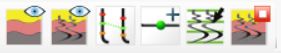
![]() Cross
Section Properties:
Open the Cross Section Properties dialog box to
adjust the appearance of the cross section.
Cross
Section Properties:
Open the Cross Section Properties dialog box to
adjust the appearance of the cross section.
![]() Model Properties: Open the Model Properties dialog box to
adjust the appearance of the model.
Model Properties: Open the Model Properties dialog box to
adjust the appearance of the model.
![]() Add/Edit
Correlation:
Open the Edit Correlations dialog
box to add, edit, and delete correlations, and adjust their appearance.
Add/Edit
Correlation:
Open the Edit Correlations dialog
box to add, edit, and delete correlations, and adjust their appearance.
![]() Add/Move
Point:
Click to enter editing mode and change how the correlations are draw
between the wells.
To add a point hover over the correlation between two wells, which will
be highlighted, and once highlighted, left click and drag it to where
you want it to be. To move a point, hover
over the correlation point, which will be highlighted as a larger
point, and once highlighted, left click and
drag it to where you want it to be. Press the stop button to get out of
the mode.
Add/Move
Point:
Click to enter editing mode and change how the correlations are draw
between the wells.
To add a point hover over the correlation between two wells, which will
be highlighted, and once highlighted, left click and drag it to where
you want it to be. To move a point, hover
over the correlation point, which will be highlighted as a larger
point, and once highlighted, left click and
drag it to where you want it to be. Press the stop button to get out of
the mode.
![]() Edit
Well
Tops: Add, edit, or remove a top.
Edit
Well
Tops: Add, edit, or remove a top.
![]() or
or
![]() Display
Model: Open
the 2D Model
window. When the icon has a green check mark the model window
is open.
Display
Model: Open
the 2D Model
window. When the icon has a green check mark the model window
is open.
Also See
— MORE INFORMATION

|
Copyright © 2020 | SeisWare International Inc. | All rights reserved |