Attribute Calculator
The
Attribute Calculator application
allows you
to run a several different attribute calculations over your dataset.
The final
result is a SEG-Y volume which can be generated for both 2D
and 3D lines. To view any volume in map view, you must create a slice
of the generated SEG-Y file from the Create Slice File
application.
- Select one or more seismic
lines to
be used in the generation. Click on the Dataset
cell to select a different version of the line.
- Select the Operation.
- Specify your Data
Windows. These
values must be odd numbers.
- Change the Output
Window
parameters.
By default the entire line is selected.
- Fill in your Output
Parameters. Note:
Parameters are not saved with the file, so the description
should be as descriptive as possible.
- (Optional) Change the Output
Folder
and the Working
Set flag. Note:
In most cases you won't
want your attribute
volume to belong to your working set.
- Click
 .
.
Once the new version of the line has been created it will be
visible in Line
Properties, and be available in
seismic selection dialogs. For each
operation you will create one new file with a File Type
determined by the
operation name.
General Information
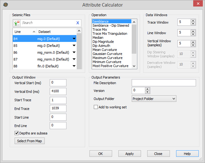
Seismic Files
Select the files you want to use in your attribute calculation. The working set version is listed, but alternate datasets can be selected by clicking on the down arrow in the Dataset cell. Left click to select a seismic file, use the Ctrl key on your keyboard to select multiple seismic files. or select a group of seismic files from the Basemap. Note: If you select multiple files, not all Output Window fields can be specified.
To help you make your file selections, you can sort any column by left
clicking
on the column header, you can apply a filter
(![]() ), or
you can type a search string
into the search
bar to limit the list using Line,
and Dataset
information.
), or
you can type a search string
into the search
bar to limit the list using Line,
and Dataset
information.
For additional selection and navigation options right click on the Seismic Files list
to access
the shortcut
menu.
Operation
Choose the operation(s)
that will be run on the selected files.
If running volume curvature, since it is so compute
intensive,
select all of the volume curvatures (and dip steering semblance if
desired) at once, since the most of the computations is in the
calculation of dip and not in the actual curvature equation.
Data Windows
Trace Window:This specifies how many traces to use in the operation. It is the M in the semblance equation. This should always be an odd number.
Line Window: This specifies how many lines to use in the semblance algorithm. It is not used for trace mix. It is the L in the semblance equation. This should always be an odd number. For 2D lines, this option is not used.
Vertical Window:This specifies how many samples to use in the semblance algorithm. It is not used for trace mix. It is the N in the semblance equation.
Dip Steering Window:This specifies how many samples to use in the dip steering semblance algorithm or any of the curvature algorithms. It specifies the number of dip cubes that will be tested.
Derivative Window:When using any of the curvature algorithms, this specifies how many dips across are used when calculating the derivative of the dip.
Output Parameters
File Description:Type in a description for the file. This description will appear in the line properties and other dialogs. The description is optional.
Version:Specify
a version
number for the output files. This number helps to uniquely identify a
dataset.Output
Folder:Specify where to put the
output files.
Project Folder: Place the output file in the main project folder.
Data Folder: Place the output file in the project's data folder. Often this will be the same as the Project Folder.
Same As Input: Place the output file in the same folder as the source SEG-Y file. This can aid in project maintenance when sharing projects across a network.
Add to Working Set: When set the output file automatically becomes a member of the working set.
Output Window
Normally
you will modify these values in order to reduce the size of the
associated output
file.
Vertical Start:Specify the vertical start for the output file. The default is the start of the input file.
Vertical End:Specify the vertical end for the output data file. The default is the end of the input file.
Start Trace:Specify the start trace for the output file. The default is the start trace of the input file.
End Trace:Specify the end trace for the output data file. The default is the end trace of the input file.
Start Line: Specify the start line for the output file. The default is the start line of the input file.
End Line:Specify the end line for the output data file. The default is the end line of the input file.
Depths are Subsea: When checked this specifies the vertical window of depth data in subsea. When unchecked values are in true vertical depth. This has no effect on time data.
 Select
From Map: Instead
of
manually entering extents you can select the extents of the volume to
be used in the calculation from the map. Click on the Select From Map
button, then select an area of a 3D
survey. Click and release the left mouse button on the 3D
survey
to select the start, and then left click again on the 3D survey to
select the end. This is very useful when trying to select an
area
that doesn't encompass the entire 3D survey. If you hit the
Select
From Map button by
accident, click on it again to cancel the map
selection.
Select
From Map: Instead
of
manually entering extents you can select the extents of the volume to
be used in the calculation from the map. Click on the Select From Map
button, then select an area of a 3D
survey. Click and release the left mouse button on the 3D
survey
to select the start, and then left click again on the 3D survey to
select the end. This is very useful when trying to select an
area
that doesn't encompass the entire 3D survey. If you hit the
Select
From Map button by
accident, click on it again to cancel the map
selection.
Also see
— MORE INFORMATION

|
Copyright © 2020 | SeisWare International Inc. | All rights reserved |