Project Performance Management
Use the following information to optimize the performance of your project.
| Disable Cascade Technology™ |
When you are performing a series of changes, especially in a large project, click |
| Convert SeisWorks seismic data | If you convert your SeisWorks volume to a 3dr volume, you can work on your local machine rather than over a network. In the 3D View window, from the File menu select Import then Convert 3dv to 3dr. |
| Optimize OpenWorks data loading options | Load as Needed: Use this option for large projects with many data types, especially if you only need a part of the dataset. Only basic project data is loaded initially (i.e. well lists, surface / pick names, etc.), but not the underlying data (pick data, log curves, interval data, etc.). Specific data is loaded later, as needed, when it is used in the project. For example, when you select a log to display for a well, all the log curves for that well are downloaded and the selected one is displayed, and when you select a pick or surface, all the pick data for that surface are downloaded. This can save you time because you only load the data you need, and don't load the data you never use; however, the first time you access specific data, you will experience a delay while that data is downloaded from OpenWorks. Once the data has been downloaded, data access is the same as with the Load All Data Now option. Load All Data Now: Use this option for smaller data sets, or for large datasets when you expect to use all or most of the data, or when the project start up time is not an issue. ll the project data is loaded at start up. For larger projects, this can take a significant amount of time. Allows faster initial working access to data, since all the data is already loaded. |
| Increase gridding increments | In general, the smaller the gridding increment, the more grid rows and columns are generated, resulting in a more accurate structural surface grid. However, more grid rows and columns mean more nodes are generated, and therefore more resources are used making the process longer and more memory intensive. When the increment is set higher, fewer rows and columns are generated and less smoothing is applied, which means faster rendering, but with the potential of a less accurate structural grid. If the increments are set too high, the grid contours may appear blocky or angular. A general guideline is to set the increment at twice the distance as the average distance between wells. To change the gridding increment, in the 3D View or Map View window, on the Buttons toolbar click  , and navigate to the Projects tab. , and navigate to the Projects tab. |
| Turn on well log curve filters |
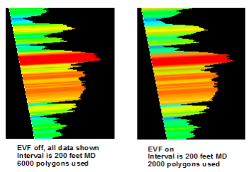 With a large number of well points and very small curve increments, you should apply a filter in both the 3D View and Cross Section Viewwindows. This filter reduces the number of polygons rendered by applying a localized min/max filter to remove small variations in the log curve (noise), while preserving the character of the log and maintaining the local minimum and maximum values. In general, if you have less that 100 wells. For less than 100 wells you don't need a filter. For 100 to 500 wells, try a filter increment of 20- With a large number of well points and very small curve increments, you should apply a filter in both the 3D View and Cross Section Viewwindows. This filter reduces the number of polygons rendered by applying a localized min/max filter to remove small variations in the log curve (noise), while preserving the character of the log and maintaining the local minimum and maximum values. In general, if you have less that 100 wells. For less than 100 wells you don't need a filter. For 100 to 500 wells, try a filter increment of 20- |
| Monitor framerate and graphics performance |
In the 3D View window, on the General tab the 3D View Display Controls dialog box, and turn on Framerate and Graphics Performance. These values vary widely from system to system, but can monitor these numbers to determine when decreased performance occurs. |
| Display fewer well log curves and templates |
The number of wells selected and displayed in 3D affects the total number of polygons displayed. Select only the wells you need. |
| Control the number of polygons being displayed |
The number of tracks and curves in your well log template affects the total number of polygons displayed. Well paths, template backgrounds, frames around curves, and fancy fonts all carry a lot of polygons. Reduce the number of tracks, curves, and annotations being displayed. |
| Reduce the OpenWorks well list size |
Review the OpenWorks well list used for your project to see if all the wells are needed. You can create a well group that is a subset of the total list and send to OpenWorks to use as the preferred well list. |
| Optimize the number of surfaces displayed in the framework |
The number of surfaces displayed affects the total number of polygons displayed. Select only the surfaces you need to display. |
| Optimize the number of active surfaces |
Instead of making all the surfaces Active in case you might need them in other dialogs, turn off the ones you know you won’t need. |
| Turn off Conformability and Dynamic Termination | If you are performing multiple operations that cause display updates, turn off the Conformability and Dynamic Terminations settings temporarily. When you complete the operations, turn the settings back on. |
| Turn off Instant Auto Save |
All pick interpretations are automatically saved to the autoSaved.pix file in the picks subdirectory. If you have a large project (e.g. >10,000 wells), saving the autoSaved.pix file may take a few seconds every time you edit a pick. To override this, turn off the Instant Auto Save feature in the Quick Pick dialog box. The picks are saved to memory, and then you can save all picks to the autoSaved.pix file by clicking the Save Picks icon ( |
| Limit your Z range |
Limit your Z range to a reasonable depth range for interpretation. This will limit the number of points and polygons you draw and capture to hardcopy. |
| Use Dynamic AOI changes | Instead of looking at your entire project area, look at specific areas at a time. You can leave the project limits unchanged and the grids will remain unchanged, while rendering smaller areas of the project at a time. |
| Avoid converting large point sets to inter-well picks |
Many seismic horizon/point set corrections can be done using a small number of picks and conformability. |
| Optimize the size of your cross sections |
The smaller the cross section, the fewer polygons to be rendered. Cover only the area you need. |
| Turn off Gouraud Shading | Instead of interpolating the shading and colors, use the Discrete Coloring setting |
— MORE INFORMATION

|
Copyright © 2020 | SeisWare International Inc. | All rights reserved |