Project Tools: Limits
The Limits dialog box is used to set the limits for the display and for the project, determining and area of interest (AOI) or volume of interest (VOI). AOI and VOI limits are used in other dialog boxes throughout the project to determine how data is displayed. To open the Limits dialog box, click  on the Buttons toolbar in the 3D View or Map View window, or from theEdit menu in the 3D View window, select Limits.

Menus
There is a menu at the top of the Limits dialog box that allows you to load and save display limits file, simplifying the process of changing the limits of the display or the project.
File Menu: The file menu contains options to save the project, and to save and load display and project limits files. ![]() See File menu options...
See File menu options...
Display Tab
The settings on the Display tab control the display AOI and VOI the 3D View and Map View windows. These values can affect the amount of data being displayed, but clipping options often need to be applied in separate dialog boxes. The display limits will control how much of a surface is visible on the Map View window. The amount of data being used to generate the surface is controlled by the project limits.
X: Enter Min and Max values to determine the limits of the display in the east/west direction. You can also use the icons at the bottom of the tab or load a saved *.lim file to automatically populate these fields.
Y: Enter Min and Max values to determine the limits of the display in the north/south direction. You can also use the icons at the bottom of the tab or load a saved *.lim file to automatically populate these fields.
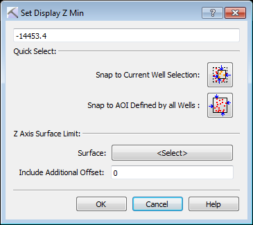
Depth (TVDSS): Click to open the ![]() Set Display Z Min or Set Display Z Max dialog box to enter a Min orMax TVDSS value, or select a surface and offset to determine the limits of the display in depth. You can also use the icons at the bottom of the tab or load a saved *.lim file to automatically populate these fields.
Set Display Z Min or Set Display Z Max dialog box to enter a Min orMax TVDSS value, or select a surface and offset to determine the limits of the display in depth. You can also use the icons at the bottom of the tab or load a saved *.lim file to automatically populate these fields.
![]() Snap Display AOI to Selected Wells: Automatically determine the X, Y, and Depth (TVDSS) values using the minimum and maximum values for all of the wells that are currently selected.
Snap Display AOI to Selected Wells: Automatically determine the X, Y, and Depth (TVDSS) values using the minimum and maximum values for all of the wells that are currently selected.
![]() Snap Display AOI to ALL Wells: Automatically determine the X, Y, and Depth (TVDSS) values using the minimum and maximum values for all of the wells that are currently in the project.
Snap Display AOI to ALL Wells: Automatically determine the X, Y, and Depth (TVDSS) values using the minimum and maximum values for all of the wells that are currently in the project.
![]() Snap Display AOI to Project AOI: Automatically determine the X, Y, and Depth (TVDSS) values using the corresponding values on the Project tab.
Snap Display AOI to Project AOI: Automatically determine the X, Y, and Depth (TVDSS) values using the corresponding values on the Project tab.
Project Tab
The settings on the Project tab control the project AOI and VOI the 3D View and Map View windows, as well as the grid increments, used to determine how surfaces are calculated and displayed, and the corresponding row and column values. Data outside of the project limits is do used to generate surfaces.
X: Click on a cell to enter Min, Max, Increment and Rows/Cols values.
Min/Max: Enter values to determine the limits of the display in the east/west direction. You can also use the icons at the bottom of the tab or load a saved *.lim file to automatically populate these fields.
Increment: Enter a grid increment value to determine the grid spacing for displayed surfaces in the east/west direction. Changing the Increment will affect the Rows/Cols value, which is determined by taking the total range and dividing it by the Increment. See the note on increments below.
Rows/Cols: Enter a value to determine the number of rows contained in the displayed surfaces. Changing the Row/Cols value will affect the Max value, which is determined by taking the Min value and adding the Increment multiplied by the number or Rows.
Y: Click on a cell to enter Min, Max, Increment and Rows/Cols values.
Min/Max: Enter values to determine the limits of the display in the north/south direction. You can also use the icons at the bottom of the tab or load a saved *.lim file to automatically populate these fields.
Increment: Enter a grid increment value to determine the grid spacing for displayed surfaces in the north/south direction. Changing the Increment will affect the Rows/Cols value, which is determined by taking the total range and dividing it by the Increment. See the note on increments below.
Rows/Cols: Enter a value to determine the number of columns contained in the displayed surfaces. Changing the Row/Cols value will affect the Max value, which is determined by taking the Min value and adding the Increment multiplied by the number or Columns.
Depth (TVDSS): Enter Min and Max values to determine the limits of the display in the depth. You can also use the icons at the bottom of the tab or load a saved *.lim file to automatically populate these fields. You can also use the icons at the bottom of the tab or load a saved *.lim file to automatically populate these fields.
A Note on Increments
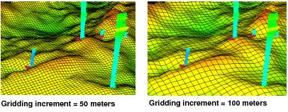
Changes to the increment will affect the surfaces being displayed in the Map View and 3D View windows. The smaller you make the X and Y Increments, the more grid rows and columns will be generated, resulting in a more accurate structural surface grid. The gridding increment is dependent on the volume of data, project area covered and well density. As a rule of thumb, use twice the average distance between wells to determine the Increment values. You can also adjust these values based on the project area, the larger the area, the larger the increment.
— MORE INFORMATION

|
Copyright © 2020 | SeisWare International Inc. | All rights reserved |