3D View Tools: 3D Cross Section Display Controls
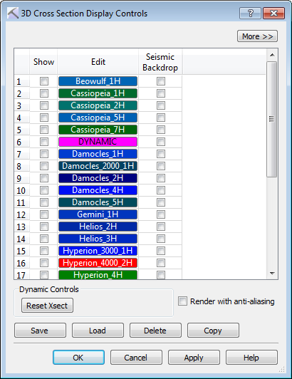 The 3D Cross Section Display Controls dialog box is used to select one or more existing cross sections to display in the 3D View window, turn on a seismic backdrop, and reset cross section after it has been dynamically moved. To open the 3D Cross Section Display Controls dialog box, click
  on the Buttons toolbar, or from the Edit menu select 3D Sections.
Cross Section and Seismic Controls
 /
/ More/Less: Click to display the seismic controls for the section. You need to load seismic data for these to be applicable. Click to display only the list of existing cross sections.
Column Definitions
Show: Place a check mark next to each cross section you want to display.
Edit: Click on a cross section to open the Edit Cross Section window to edit the name, color, and behavior of the cross section, and determine which surfaces and faults are projected onto the surface of the section.
Seismic Backdrop: Place a check mark next to each cross section for which you want to display a seismic backdrop. Click to change the display parameters for the seismic backdrop.
Note: The seismic display parameters listed below are available in both the 3D Cross Section Display Controls dialog box accessed from the 3D View window, and the Select Cross Section dialog box accessed from the Cross Section View window. You can change the parameters from either location.
Seismic Depth Shift: Enter a shift value in meters to determine the start depth of the seismic section.
Seismic Spectrum: Open the Seismic Spectrum Manager and select a color spectrum for the seismic backdrop.
Spectrum Colors: When a Seismic Spectrum is selected, this cell will display a preview of the spectrum.
Spectrum Min.: The amplitude value assigned to the left-most color on the spectrum.
Spectrum Max.: The amplitude value assigned to the right-most color on the spectrum.
Data Min.: The minimum amplitude value in the seismic data. This is informational and can be used to assign a Spectrum Minimum value.
Data Max.: The maximum amplitude value in the seismic data. This is informational and can be used to assign a Spectrum Maximum value.
Data Mean: The average amplitude value in the seismic data.
Source: The source of the seismic data.
Dynamic Controls
 Reset Xsect:Reset the position and orientation of the displayed cross section.
Other Options
Use the buttons at the bottom of the dialog box to save, load, delete, and copy the section.
 Save: Save the selected cross section to a file.
 Load: Load a cross section file (*.xsec) into your project.
 Delete: Delete the selected cross section. This will permanently remove the section from your project.
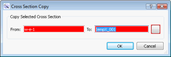
 Copy: Open the Cross Section Copy dialog box. Enter a name for the new cross section, and then click on the color field to open the Color Table and change the cross section line color.
Render with Anti-aliasing: Turn this on to reduce the distortion artifacts using an anti-aliasing technique.
— MORE INFORMATION

|
Copyright © 2020 | SeisWare International Inc. | All rights reserved |