3D View Tools: 3D Pick Display
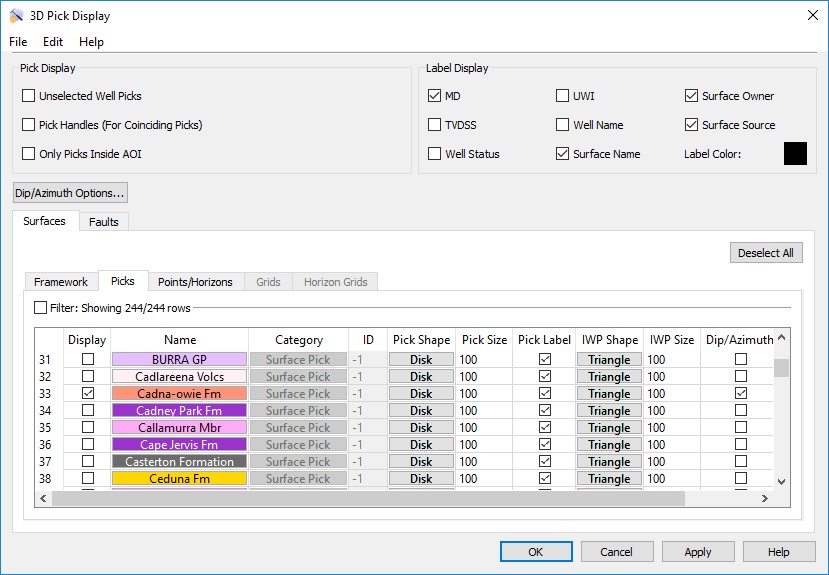
Use the 3D Pick Display dialog box to determine which surface picks, fault picks, and inter-well picks will appear in the 3D display, and manage their appearance. To open the 3D Pick Display dialog box, click  on the Buttons toolbar, or from theView menu select Picks.
Menus
A series of menus are available at the top of the dialog box to access additional tools and options.
File Menu: Use the File menu to save, and export fault sets. ![]() See File menu options...
See File menu options...
Edit Menu: Select Data to open the Edit Picks dialog box to view, edit, and deleted well pick data.
Pick Display Controls
Specify for which wells picks will be displayed, and the behavior when multiple picks exist.
Unselected Well Picks: Display the selected picks for all wells, not just selected wells.
Pick Handles (For Coinciding Picks): Display graphical handles on coinciding picks to make them easier to edit.
Only Picks Inside AOI: Only display picks inside the area of interest (AOI) specified on the Display tab in the Limits dialog box.
Label Display Controls
Select the items to include on the pick label. Note that you also need to turn on the Pick Label from the Surfaces or Faults tab for the label to display.
Pick Labels: Turn on the items you want to display on the pick label. Choose from MD, UWI, Interpreter, TVDSS, Well Name, Well Status, Surface Name, Surface Owner, and Surface Source. Note: Surface Owner and Surface Source are only available when Surface Name is toggled on.
Label Color: Click on the color field to open the Color Table to select or change the default color for the pick labels.
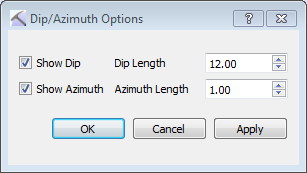
Dip/Azimuth Options
Note that you also need to turn on Dip/Azimuth from the Surfaces or Faults tab for the markers to display.
 Dip/Azimuth Options: Open the Dip/Azimuth Options dialog box to enable dip and azimuth displays.
Show Dip: Turn on a dip marker, which will appear as a line extending perpendicular to the pick marker, drawn in the pick color.
Dip Length: Enter a relative length for the dip marker. The maximum value is 99.9.
Show Azimuth: Turn on an azimuth marker, which will appear as a line parallel to the pick marker.
Azimuth Length: Enter a relative length for the azimuth marker. The maximum value is 99.9.
Surfaces and Faults Tabs
Use the Surfaces and Faults tabs to select the surface and fault pick you want to display, and adjust their display properties. You can turn on data from any tab. Each tab contains the associated display options for each data type, as well as informational fields that can't be edited. You need to move data to the Framework tab from the Surface Display and Data dialog box in the3D View window.
 Deselect All: Remove the check mark from the Display column for all surfaces on all tabs.
Column Headings
The following is a list of definitions for the columns found of the Framework tab. Note that the other tabs will only have the columns relevant to the specific data type. You need to move data to the Framework tab from the Surface Display and Data dialog box in the3D View window.
Display: Place a check mark next to each all of the surface and fault picks you want to display.
Name: The name and color of the surface. Click on the name to open the Change Surface Color dialog box to change the color of the surface for the entire project. On every other tab, click on the name to open the Copy Surface or Change Surface Color dialog box to create a copy of the surface with a different name, or change the surface color of the surface for the entire project.
Category: The surface type. This informational column is useful on the Framework tab where multiple data types can be present.
ID: Any value other than “-1” indicates that the data was loaded from OpenWorks. This column is for information only.
Pick Shape: Select a shape style for the pick markers. Choose from None, Triangle, Square, Disk, Sphere, or Box.
Pick Size: Enter a value in map units to determine the size of the pick markers.
Pick Label: Display a pick label showing the items selected from the Label Display options.
IWP Shape: Select a shape style for the inter-well markers. Choose from None, Triangle, Square, Disk, Sphere, or Box.
IWP Size: Enter a value in map units to determine the size of the inter-well pick markers.
Point Shape: Select a shape style for the points markers. Choose from None, Triangle, Square, Disk, Sphere, or Box.
Point Size: Enter a value in map units to determine the size of the points markers.
Dip/Azimuth: Orient the marker using the associated dip and azimuth values, and display dip and azimuth markers when enabled.
— MORE INFORMATION

|
Copyright © 2020 | SeisWare International Inc. | All rights reserved |