Cross Section View Tools: Select Surface for Cross Section
Use the Select Surface for Cross Section dialog box to select the surfaces to display on the cross section, and manage their appearance. To open the Select Surface for Cross Section dialog box, click  on the Buttons toolbar, or from theEdit menu select Surfaces.
There are two tabs, Surface and Faults, that each contain a series of tabs used to select the data you want to display. Additional options are found at the bottom of the dialog box. These allow you to turn on back interpolation, a tool that will integrate wells without picks into your cross section.
Surfaces and Faults Tabs
Use the Surfaces and Faults tabs to select the surfaces and faults you want to display in your cross section, and adjust their display properties. You can turn on data from any tab. Each tab contains the associated display options for each data type, as well as informational fields that can't be edited. You need to move data to the Framework tab from the Surface Display and Data dialog box in the3D View window.
 Deselect All: Remove the check mark from the Display column for all surfaces on all tabs.
Column Definitions
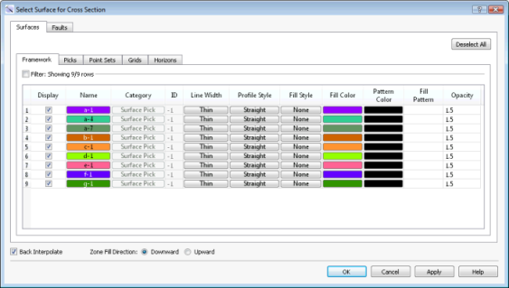
The following is a list of definitions for the columns found of the Framework tab. Note that the other tabs will only have the columns relevant to the specific data type. You need to move data to the Framework tab from the Surface Display and Data dialog box in the3D View window.
Display: Place a check mark next to each surface you want to display.
Name: The name and color of the surface. Click on the name to open the Change Surface Color dialog box to change the color of the surface for the entire project. On every other tab, click on the name to open the Copy Surface or Change Surface Color dialog box to create a copy of the surface with a different name, or change the surface color of the surface for the entire project.
Category: The surface type. This informational column is useful on the Framework tab where multiple data types can be present.
ID: Any value other than “-1” indicates that the data was loaded from OpenWorks. This column is for information only.
Conform: Displays the surface to which the selected surface was conformed. This column is for information only. You can change the conform behavior from the Surface Display and Data dialog box in the3D View window.
Conform Category: The surface type of the conform surface. This column is for information only.
Conform ID: Any value other than “-1” indicates that the conform surface was loaded from OpenWorks. This column is for information only.
Line Width: The thickness of the surface line in the cross section display. This can be set to Thin, Medium, or Thick. The line is drawn in the surface color, as indicated in the Name column.
Profile Style: The style of the surface line in the cross section display. This can be set to Straight or Wiggle. The line is drawn in the surface color, as indicated in the Name column.
Fill Style: The fill style associated with the surface. This is applied downward or upward, depending on the Zone Fill Direction selection.
None: No fill is applied.
Solid: A solid fill is applied in the specified Fill Color.
Pattern: A patterned fill is applied using the specified Pattern Color and Fill Pattern.
Solid-Pattern: A solid, patterned fill is applied using the specified Fill Color, Pattern Color, and Fill Pattern.
Fill Color: Click on the cell to open the Color Table and change the fill color. This is only applicable for Solid and Solid-Pattern fill styles.
Pattern Color: Click on the cell to open the Color Table and change the color applied to the fill pattern. This is only applicable for Pattern and Solid-Pattern fill styles.
Fill Pattern: Click on the cell to open the Lithology Pattern Selection dialog box and select the lithologic fill pattern. This is only applicable for Pattern and Solid-Pattern fill styles.
Opacity: The opacity of the surface fill. "1" indicates that the surface is fully opaque, and "0" indicates that the surface is fully transparent. Click in individual fields to enter values or use the up and down arrows. Clicking on the column header will change the Opacity value for all filled surfaces in increments of 0.1.Fill
Additional Options
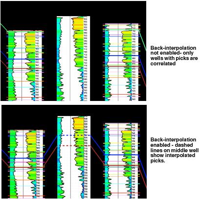 Back Interpolate: Turn on back interpolation to display interpolated picks on wells that don't contain a pick for the surface you are displaying. Back interpolated picks appear as dashed lines on the well template and log curves, and are based on the intersection of surfaces calculated from the interpreted picks. Back interpolation is only applied when you are using fixed spacing.
Zone Fill Direction: Indicate if the fill should be extended from the surface downward or upward. This is applied to the entire cross section.
— MORE INFORMATION

|
Copyright © 2020 | SeisWare International Inc. | All rights reserved |