Cross Section View Tools: Cross Section Pick Display
The Cross Section Pick Display dialog box is used select which surfaces and faults are being displayed in the cross section, and control how they appear. To open the Cross Section Pick Display dialog box, click  on the Buttons toolbar, or from theView menu select Picks.
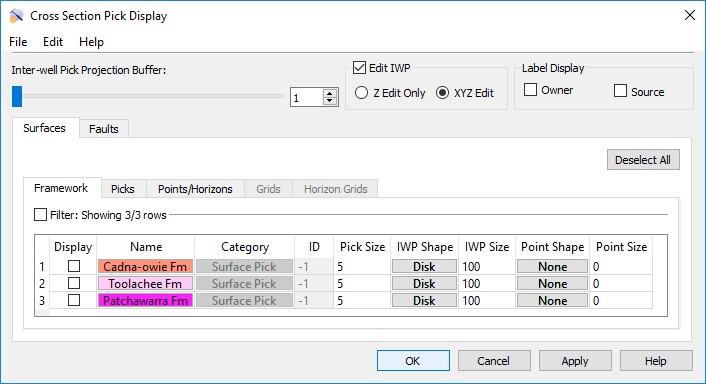
The Cross Section Pick Display dialog box has a series of menus used to access data options, options to control the behavior of inter-well picks, and two tabs that each contain a series of tabs used select the picks you want to display in your cross section.
Menus
File Menu
Save Project: Save your project to the default session file, default.ini. This will save unsaved data changes as well as project settings.
Import: Select from a list of import options.
Export: Select from a list of export options.
Edit Menu
Data: Open the Edit Picks window to view, analyze, and edit picks information.
Inter-well Pick Controls
Inter-well Pick Projection Buffer: Use the slider or enter a projection distance to determine the maximum distance at which inter-well picks well be projected onto the cross section.
Edit IWP: Place a check mark in this field to edit inter-well picks in the cross section.
Z Edit Only: Allow inter-well picks to be moved in the Z-direction only.
XYZ Edit: Allow inter-well picks to be moved in all directions.
Label Display Controls
Select the items to include on the pick label.
Label Display: Turn on the items you want to display on the pick label. Choose from Owner and Source.
Surfaces and Faults Tabs
Use the Surfaces and Faults tabs to select the surface and fault pick you want to display in your cross section, and adjust their display properties. You can turn on data from any tab. Each tab contains the associated display options for each data type, as well as informational fields that can't be edited. You need to move data to the Framework tab from the Surface Display and Data dialog box in the3D View window.
 Deselect All: Remove the check mark from the Display column for all surfaces on all tabs.
Column Headings
Display: Place a check mark next to each all of the surface and fault picks you want to display.
Name: The name and color of the surface. Click on the name to open the Change Surface Color dialog box to change the color of the surface for the entire project. On every other tab, click on the name to open the Copy Surface or Change Surface Color dialog box to create a copy of the surface with a different name, or change the surface color of the surface for the entire project.
Category: The surface type. This informational column is useful on the Framework tab where multiple data types can be present.
ID: Any value other than “-1” indicates that the data was loaded from OpenWorks. This column is for information only.
Pick Size: Enter a value in vertical units to determine the size of the pick marker.
IWP Shape: Select a shape style for the inter-well pick markers. Choose from None, Star, Plus, Disk, Square, or Diamond.
IWP Size: Enter a value in project units to determine the size of the inter-well pick markers.
Point Shape: Select a shape style for the point markers. Choose from None, Star, Plus, Disk, Square, or Diamond.
Point Size: Enter a value in project units to determine the size of the point markers.
— MORE INFORMATION

|
Copyright © 2020 | SeisWare International Inc. | All rights reserved |