3D Data Tab: Select the file to load into the project. This tab contains 3 tabs which allow you to load files from different sources.  See 3D Data tab options...
3D Data Tab Options
There are three tabs used to select seismic data. Once you select a file, the tabs at the bottom of the dialog box will become active.
SeisWorks Tab
A list of available projects will appear in the left pane. Click on a project to see a list of files associated with the project. Select the file that you want to see in your project.
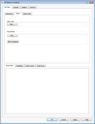
SEG-Y Tab
Select a seismic file and corresponding parameter file. If a parameter file doesn't exist, open the SEG-Y Analyzer.
 SEG-Y File: Select a SEG-Y file (*.segy, .*sgy) to load into the project.
Parameter File: Select a parameter file to associate with the selected SEG-Y file. Click  if one doesn't exist.
SEG-Y Analyzer: Open the SEG-Y Analyzer to create a 2D or 3D parameter file.
3dr tab
Select an existing 3dr or StratalSlice file.
3dr File: Select a 3dr (.3dr) volume.
Data Tabs
After loading a file, additional information and options become available.
Active File: This tab displays header and summary information for the selected file. Use the scroll bars or resize the dialog if needed to view the rest of the data.
Sampling: On this tab, use the slider to balance the quality with performance. 1 represents high quality and 10 represents high performance.
Domain Tab: Specify the seismic domain options. See Domain tab options...
Domain Tab Options
Depth: Select this option when you are displaying data recorded in depth.
Interval: Enter the sample interval of the data being displayed.
Datum: Specify the depth datum of the data being displayed, and specify the units. Note: Changing the units will not convert the file values.
Time: Select this option when you are displaying data recorded in time. You will need a checkshot file to convert time values into depth. Once loaded, you can view and edit the values in the file.
 Load OpenWorks Checkshot data: Select a checkshot file from OpenWorks.
 Checkshot File: Select a checkshot file (.ckshot). The data will appear in the table, where it can be viewed and edited.
Datum: Specify the depth datum of the data being displayed, and specify the units. Note: Changing the units will not convert the file values.
Time: Select the units used for the time values in the checkshot file.
Depth: Select the units used for the depth values in the checkshot file.
 Add: Add a new row to the table.
 Delete: Remove the selected row from the table.
 Save As: Save changes to a new checkshot file (.cksht).
 Restore: Undo all changes since the last save.
Display Tab: Manage the appearance of the seismic data in your display. See Display tab options...
Display Tab Options
The display tab contains two tabs, used to select the which slices to display, and is used to select the color and opacity spectra.
3D Tab
Use these options to display individual slices. Turn on the Line, Trace, or Slice displays, and then use the sliders to change the slice being displayed.
Step: Enter a step value associated with the up and down arrows used when changing the slice being displayed.
 Clear: Clear the slice from the display.
 Build Cross Section: Automatically create a cross section for the current Line or Trace being displayed. This will allow you to display the seismic data as a backdrop in the Section View window.
First Line/Last Line: The first and last lines in the file as read from the header.
Fence Diagram Tab
Use these options to display multiple slices at regular intervals. Turn on the Line, Trace, or Slice displays, and then specify First and Last slices to display, as well as the Increment.
Additional Options
Active Color Spectrum: Click on the color spectrum to open the Seismic Spectrum Manager to edit or change the seismic color spectrum.
Active Opacity Spectrum: Click on the opacity spectrum to open the Opacity Spectrum Manager to edit or change the seismic opacity spectrum.
Show slice drag anchors: Turn this on to display anchors that can be used to change the slice being displayed by dragging the slice in the 3D View window. This is not available for fence diagrams.
Horizon Tab: Select seismic horizons to import into the project and set the import parameters. See Horizon tab options...
Horizon Tab Options
The horizons imported from this tab are added to the Horizons tab on the Surfaces tab of the Surface Display and Data dialog box.
Filter: Filter the list of available horizons using a string search, or by selecting a specify horizon type. Click  to apply the search filter.
Select Horizons for Import: Select the horizons that you want to import.
Import Options: Place a check mark next to the options you want to apply when you import the file.
Overwrite Existing Horizons: Horizon will replace existing horizon data with the same name.
Create Point Set of Imported Horizons: Create a point set for each horizon being imported. For large data sets this may take some time.
 Import: Import the selected horizons. using the specified import options.
 . There are four tabs that are used to select a select and load a seismic file, and adjust its appearance.