Defining 3D Keywords
The SEG-Y File Viewer is used to examine SEG-Y files and to specify the location of certain critical keywords during data loading.
Defining keywords is one of the most important steps performed during data loading. You need to define keywords so that crucial information can be extracted from the headers of the SEG-Y file.
How do I define keywords when loading 3D data?
You
can use the  button
to load a previously created Keyword file. If you do not have
an existing keyword file define you will need to create one. For 3D
lines, you must
define keywords for:
button
to load a previously created Keyword file. If you do not have
an existing keyword file define you will need to create one. For 3D
lines, you must
define keywords for:
- Line Sequence Number (Inline)
- Trace Sequence Number (Crossline)
- Coordinate X
- Coordinate Y
- Click
 and to open the SEG-Y Viewer
window.
and to open the SEG-Y Viewer
window. - Change the Data View to
"Trace Header". The keywords are located in the Trace Header, however
they can be in any of the available Formats.
- Switch
the Format
until you see numbers
that
are recognizable. You will usually see the Keywords in Integer
(32
bit), IBM floating-point, or IEEE floating-point formats.
- Define the Line Sequence keyword. The Line Sequence Number increments at the end of every line after incrementing through every trace. The graph for this keyword resembles a staircase. As you scroll through the traces you are looking for a number that isn't changing.
- Scroll
through the traces to find the Line Sequence Number by using
the
slider
(
 )
or by using the arrows next to the slider.
)
or by using the arrows next to the slider. - Click on the Line Sequence Number and ensure that the cursor is blinking within the number.
- Click
the graph icon
 at
the
top of the SEG-Y Viewer. This opens the Graph Header
Word
window.
at
the
top of the SEG-Y Viewer. This opens the Graph Header
Word
window. 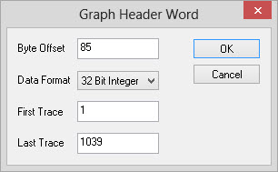
- Enter a value of "5000" in
the Last
Trace Field. If you find that
this doesn't show enough data in your graph you can increase this value.
- Click
 to
graph the data.
to
graph the data. - Check that the graph looks
like a staircase resembles
this Sample
Graph.
- Close
the graph. If think you've correctly identified the Line
Sequence Number
continue to the next step, otherwise repeat steps i. to vi. until
you've
located the Line Sequence Number. Remember that you may need to switch
the Format
if you can't find
the right value.
- Click on the key
icon
 .
This opens the Add Keyword window.
.
This opens the Add Keyword window.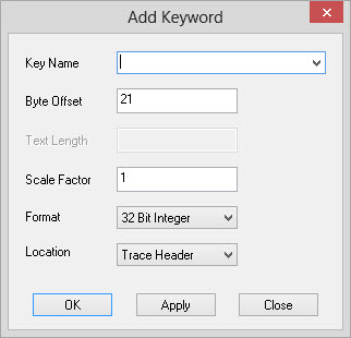
- From
the drop-down list beside Key
Name, select
"Line
Sequence Number"
and click .
You will now see the keyword defined on the right hand
side of the SEG-Y Viewer.
- Define the Trace Sequence
Number keyword using the steps listed
above.
The
Trace Sequence Number increases by 1 until the Line Sequence Number
increments, at which point the Trace Sequence Number drops to its
starting point
and begins increasing again. The graph for this keyword resembles a
sawtooth. (Sample
graph)
- Define the Coordinate X and
Coordinate Y using the steps listed
above. These are usually located side by side, and are easy to
recognize. If you don't see values that look like the coordinates in
your project, try changing the Format
. Because some formats do not store
decimals, the coordinate values may contain an extra digit.
If
this is the case you'll need to apply a Scale Factor
in the Add Keyword window.
The graphs for these keywords may resemble stairs or saw teeth. (Sample Graphs)
- When all four keywords are
defined, and appear in the right hand
side of the SEG-Y Viewer, check that they are defined correctly, with
appropriate
values and decimal places.
- From
the File
menu,
select Save
Keywords As.
- Enter
a Keyword file name that you will remember and click
 .
The .kwd
extension is added to the file name.
.
The .kwd
extension is added to the file name. - Close
the SEG-Y Viewer.
— MORE INFORMATION

|
Copyright © 2020 | SeisWare International Inc. | All rights reserved |