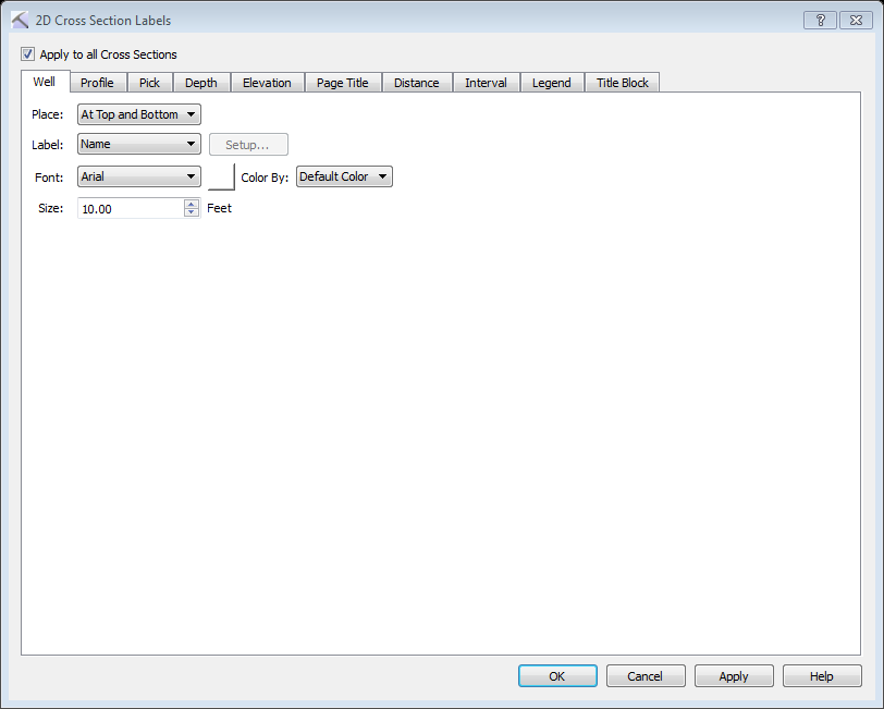
Apply to All Cross Sections: Apply the current properties to all cross sections. When this is turned off, the default settings are restored every time you open a new cross section. When this is turned on, the defined settings are applied every time you open a new cross section.
There are ten tabs, each with specific label settings.
Well Tab: Use this tab to manage the well header and trailer labels.  See Well tab options...
Well Tab Options
Place: Select the position of the well label relative to the well log display. Choose from No Label, At Top and Bottom, At Top, or At Bottom.
 Label: Select the items that you want to appear in the well label.
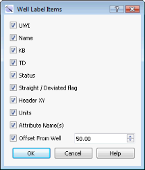
UWI: Display the UWI.
Name: Display the name of the well.
Customized: Open the Well Label Items dialog box, and select from the list of available items.
Font: Select a font style from the list.
Font Color: Click on the color field to open the Color Table and select or change the font color.
Size: Enter a size for the text in the appropriate units.
Color By: Override the default to color apply color using the well Group, or Status.
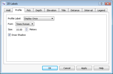
Profile Tab: Use this tab to manage the surface name labels. See Profile tab options...
Profile Tab Options
Label: Select the position of the surface label on the cross section. Choose from No Profile Label, Display Once, and Between Each Node.
Font: Select a font style from the list.
Font Color: Click on the color field to open the Color Table and select or change the font color.
Size: Enter a size for the text in the appropriate units.
Draw Shadow: Turn this on to place a shadow around the font so labels are visible when the label color resembles the background color.
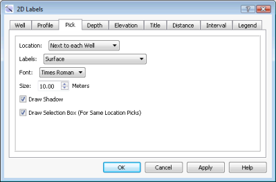
Pick Tab: Use this tab to manage the pick labels. See Pick tab options...
Pick Tab Options
Location: Select the location of the pick labels in the cross section. Choose from Off, Next to each well, or As defined by template
Labels: Select the items you want to appear in the picks label Choose from Surface, Interpreter, MDepth, Elevation, Confidence, Surface + Interpreter, Surface + Confidence, or Surface + Interpreter + Confidence.
Font: Select a font style from the list.
Size: Enter a size for the text in the appropriate units.
Draw Shadow: Turn this on to place a shadow around the font so labels are visible when the label color resembles the background color.
Draw Select Box (For Same Location Picks): Turn this on to add a selection box when there are multiple picks in the same location.
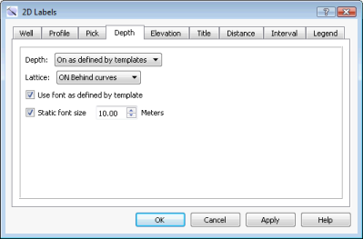
Depth Tab: Use this tab to manage the well template depth and lattice labels. See Depth tab options...
Depth Tab Options
Depth: Select the location of the depth and lattice labels in the cross section. Chose from No Depth Label, orAs defined by Template.
Lattice: Select the location of the grid lines on the template display. Choose from Off, Behind Curves, or On Top of Curves.
Use Template Defined Font: Use the font defined in the template.
Static Font Size: Turn this on to set the font size to a static value, instead of changing dynamically as you zoom in and out. Enter the font size in the appropriate units.
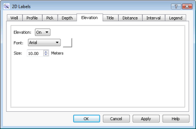
Elevation Tab: Use this tab to manage the cross-section elevation scale labels. See Elevation tab options...
Elevation Tab Options
Elevation: Turn on the elevation labels.
Font: Select a font style from the list.
Font Color: Click on the color field to open the Color Table and select or change the font color.
Size: Enter a size for the text in the appropriate units.
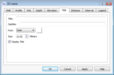
Title Tab: Use this tab to create and manage the cross section title. See Title tab options...
Title Tab Options
Title: Enter a title for the cross section.
Subtitle: Enter a subtitle for the cross section.
Font: Select a font style from the list.
Font Color: Click on the color field to open the Color Table and select or change the font color.
Size: Enter a size for the text in the appropriate units.
Display Title: Turn the title block on or off.
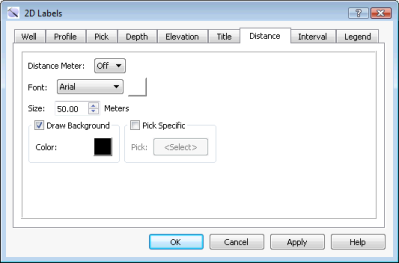
Distance Tab: Determine the display settings for Distance Spacing mode. See Distance tab options...
Distance Tab Options
In Distance Spacing mode, you can turn on an inter-well distance meter that displays the line of sight distance between the wells. This distance is determined by intersecting a constant elevation plane (SSTVD – subsea true vertical depth) with the wellbore trajectories, and calculating the distance between wells. This technique ensures that the distance between wells is accurate regardless of the well projections or cross-section scaling. When the distance meter is enabled, a double-arrow handle is attached to the elevation scale at the ends of the cross section. You can control the vertical position of the constant elevation plane by clicking and dragging the handle up or down along the scale.
If you drop the handle above the tops of the wells, the distance between the wells will be calculated based on the XY locations of their KB locations. If you drop the handle below the total depth elevations of the wells, the distance between the wells will be calculated based on the XY locations of their TD locations. Use this tab to manage the distance meter and its labels
Distance Meter: Turn the distance meter on or off.
Font: Select a font style from the list.
Font Color: Click on the color field to open the Color Table and select or change the font color.
Size: Enter a size for the text in the appropriate units.
Draw Background: Turn the on to place a background behind the distance meter.
Background Color: Click on the color field to open the Color Table and select or change the background color.
Pick Specific: Turn this on to post the distance between wells based at the location of a specific pick.
Pick: Click to open the Choose Once Surface dialog box and select a pick surface.
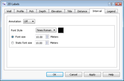
Interval Tab: In the well template, you can define a track that contains the remarks associated with an interval. Use this tab to manage the well template interval text parameters. See Interval tab options...
Interval Tab Options
Annotation: Turn the interval annotations on or off.
Font: Select a font style from the list.
Font Color: Click on the color field to open the Color Table and select or change the font color.
Font Size: Enter a font size in the appropriate units relative to the well display. The font will resize dynamically as you zoom in and out.
Static Font Size: Enter a static font size in the appropriate units. The font will not resize dynamically as you zoom in and out.
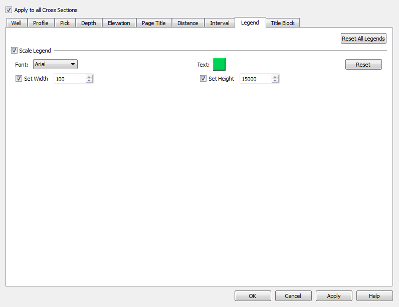
Legend Tab: Use this tab to manage the scale legend parameters. You can drag the scale legend to a new location while in Movement mode. See Legend tab options...
Legend Tab Options
Scale Legend: Turn the scale legend on or off.
Font: Select a font style from the list.
Font Color: Click on the color field to open the Color Table and select or change the font color.
Set Width: Turn this on to display a horizontal scale legend, and enter a scale display width in project units.
Set Height: Turn this on to display a vertical scale legend, and enter a scale display height in project units.
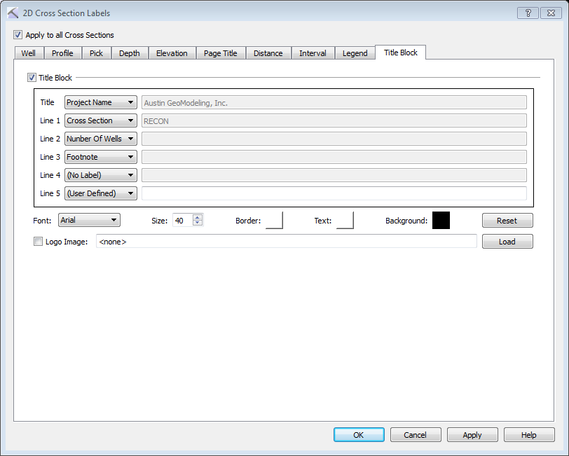
Title Block Tab: Use this tab to enter title block information, and manage its appearance. You can drag the title block to a new location while in Movement mode. See Title Block tab options...
Title Block Tab Options
Title Block: Turn the title block on or off.
Title: Select a title for the title block. Choose from a list of project attributes, or select User Defined and enter a title.
Line 1/2/3/4/5: Select from a list of project attributes, or select User Defined and enter up to 5 lines of title block text.
Font: Select a font style from the list.
Size: Enter a size for the text in the appropriate units.
Border: Click on the color field to open the Color Table and select or change the border color.
Text: Click on the color field to open the Color Table and select or change the text color.
Background: Click on the color field to open the Color Table and select or change the background color.
Logo Image: Turn this on and select a logo image to display in the title block. After selecting the image, click  .
.
 on the Buttons toolbar, or from theView menu select Labels.