Geoscience > Main Launcher > Launch Menu > Basemap > Additional Resources > Printing > Montage Editor
Montage Layout
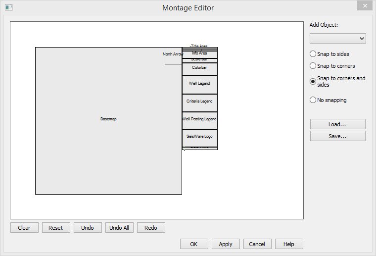
The Montage Editor allows you to customize plots by placing objects and defining their size and attributes. In addition you can attach image files created in the software, or from another applications.
The Montage Editor is opened from a Basemap Print Preview using the
Montage Editor icon ![]() .
.
Using the Montage Editor
Moving Objects
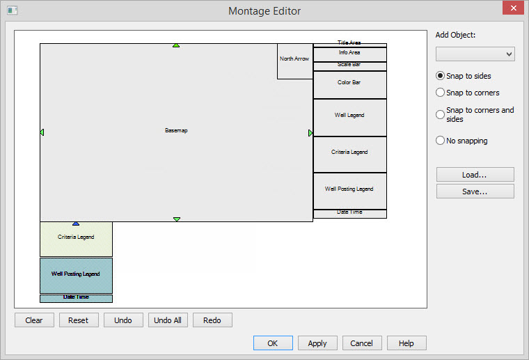
- Move the mouse over one of the objects, then click and hold the
left mouse button and start dragging the object. If the object can not
be moved, the object will highlight in red (example).
Objects that can be moved will highlight in green. All objects that are
connected to one being moved will also be highlighted but in a darker
green color (example).
- Drag the object to the desired location. Dragging an object on top
of an object that can not be connected will highlight the items in reds
to indicate that the drop can not be made (example).
Dragging the object to a location to which a connection CAN be made will highlight the object in a light green to indicate a connection on the inside of the object, or in blue to indicate a connection on the outside of the object. As objects are being dragged and the mouse (not the object edge) is close to the edge of another object, you will notice that the objects will snap to the edge of the object under the mouse. By default, the objects will snap to the outside edge (example). - Use the Control and Shift keys in the following ways to snap the
object inside existing objects, or snap to the full edge of objects in
the following ways:.
- Control: Snap to the inside edge of an object by holding the Control key while dragging (example).
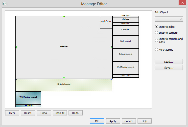
- Shift: Snap to the full edge of an object by holding to Shift key while dragging (example).
- Control and Shift: Snap
to the full edge inside another object by holding Control and Shift
while dragging (example).
- When object is in the correct position release the mouse button to place it.
Note: Snapping will always occur to the closest edge that the mouse is near. When the mouse is near a corner, the dragged object will snap to that corner.
Examples
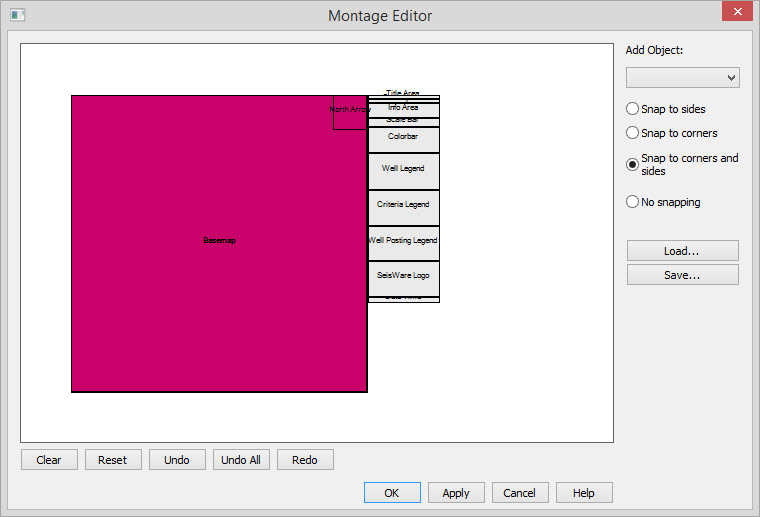 | Mouse
is over an object that can not be moved. Back to Top |
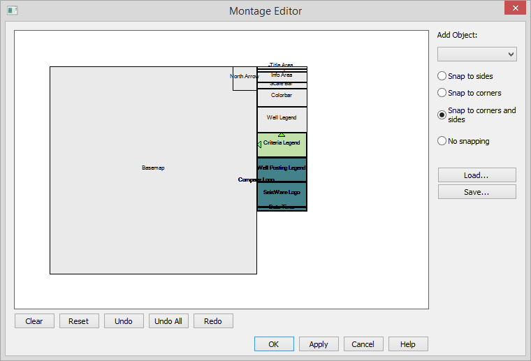 | Mouse
is over an object that can be moved. All connecting objects are
highlighted in a darker green. Back to Top |
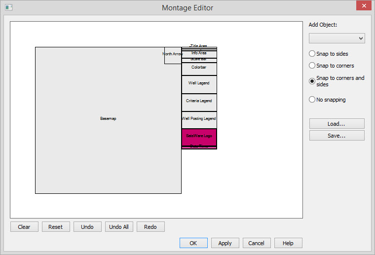 | The
objects being dragged are can not be dropped on top of this selected
object. Back to Top |
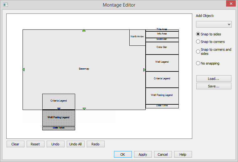
 | The
object being dragged and those connected to it are being snapped to the
outside bottom left edge of the map. Back to Top |
 | The
object being dragged and those connected to it are being snapped to the
inside bottom left corner of the map. This is done by holding the
Control key while dragging. Back to Top |
 | The
object being dragged and those connected to it are being snapped to the
outside full bottom edge of the map. The Shift is being used to make
the full edge connection. Back to Top |
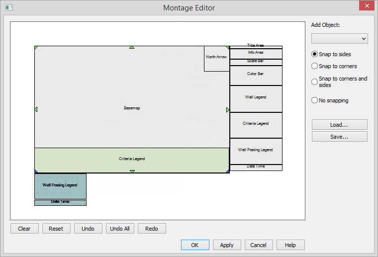 | The
object being dragged and those connected to it are being snapped to the
inside full bottom edge of the map. The control and shift keys are
being used to make the full inside edge connection. Back to Top |
Adding and Deleting Objects
How do I add an object?
You may add objects by using the drop down on the right hand side
of the dialog. The objects that can be added are:
You can remove objects in any of the following ways:
Bitmap:
Any generic user
defined bitmap. File formats supported are *.gif, *.jpeg, *.bmp, and *.png.
Colorbar: Displays a colorbar of the currently displayed ribbon values, list of the displayed ribbons, and the colorbar name and range.
Company Logo: Save a file called CompanyLogo.jpg in the Support folder of the currently installed version.
Criteria Legend: Legend of any active criteria.
Date / Time: The date and time of printing.
Info Area: Lists the project name, scale, date and optionally the user and machine names.
North Arrow: North arrow whose size and color is determined on the Legend tab of Print Properties.
Posting Legend: List all the well statuses and their symbols.
Scale Bar: Scale bar at the print scale
Title Area: Contains the title and description as entered on the Title/Desc. tab in Print Properties.
Well Legend: Displays a well symbol surrounded by any current well postings, as well as any ribboned well information.
SeisWare Logo: The SeisWare logo.
- Select the object from the Add Object drop down. It will appear
attached to the cursor, and colored green.
- Drag the object to the desired location.
- Use the Control and Shift keys in the following ways to snap the
object inside existing objects, or snap to the full edge of objects in
the following ways:.
- Control: Snap to the inside edge of an object by holding the Control key while dragging (example).
- Shift: Snap to the full edge of an object by holding to Shift key while dragging (example).
- Control and Shift: Snap
to the full edge inside another object by holding Control and Shift
while dragging (example).
- When object is in the correct position release the mouse button
to place it.
How do I Delete an Object?
You can remove objects in any of the following ways:
- Right mouse click on an object and select Delete from the menu.
- Press
 to remove all objects from the montage.
- Press
 to restore the
default montage. You can then continue to individually add and delete
objects.
to restore the
default montage. You can then continue to individually add and delete
objects.
Changing Object Attributes
To change the attributes of an object, including size, color, font and
border thickness, you can right mouse button click on the object.
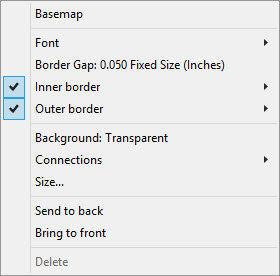
Font: Change the font settings for any text in the object
Border Gap: This
specifies the amount of gap between this object and other objects.
Inner/Outer Border: Change the setting for the object's borders.
Background: Allows you to toggle between an opaque background and a transparent background.
Width: Specify the width of the object. If an object has the left and right edges connected, then the width will display as "variable" and you will not be able to change it because the width will depend on other objects.
Height: Specify the height of the object. If an object has the top and bottom edges connected, then the width will display as "variable" and you will not be able to change it because the width will depend on other objects.
Send to back: Places the object behind all other objects. The object may no longer be visible if the objects in front are opaque.
Bring to front:Places the object in front of all the other objects. If this object is opaque, information in the other objects will be obscured.
Delete: Removes the object selected. Objects connected to the object being deleted might reposition themselves. It is best to delete objects that do not have connections first.
 Load: Press then select a previously saved
montage.
Load: Press then select a previously saved
montage.
 Save: Press to save the montage.
Font: Change the font settings for any text in the object
Name: The font name to use by
default. Be aware that some objects may over ride the font.
Height:The default font height. Again, some objects may use this default as a base reference or fully over ride it.
Bold:Set whether the default font is bold or not.
Italic:Set whether the default font is italic or not.
Underline:Set whether the default font is underlined or not.
Color:Specify the default font color.
Inner/Outer Border: Change the setting for the object's borders.
Enabled: Turns on or off the
inner/outer border.
Width:Allows you to specify the line thickness of the border.
Color:Allows you to alter the color of the border.
Width:Allows you to specify the line thickness of the border.
Color:Allows you to alter the color of the border.
Background: Allows you to toggle between an opaque background and a transparent background.
Width: Specify the width of the object. If an object has the left and right edges connected, then the width will display as "variable" and you will not be able to change it because the width will depend on other objects.
Height: Specify the height of the object. If an object has the top and bottom edges connected, then the width will display as "variable" and you will not be able to change it because the width will depend on other objects.
Send to back: Places the object behind all other objects. The object may no longer be visible if the objects in front are opaque.
Bring to front:Places the object in front of all the other objects. If this object is opaque, information in the other objects will be obscured.
Delete: Removes the object selected. Objects connected to the object being deleted might reposition themselves. It is best to delete objects that do not have connections first.
Loading and Saving Montages
When the desired display has been created it can be saved, then used to create identical plots. Load: Press then select a previously saved
montage. Save: Press to save the montage.Also See
— MORE INFORMATION

|
Copyright © 2020 | SeisWare International Inc. | All rights reserved |