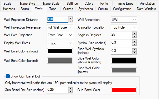
Seismic Display Properties: Wells
The Wells page allows you to specify the appearance of wells within the seismic display.
Well Projection
Well
Projection Distance: Specifies the maximum distance a well can
be from the seismic
line
in order to be displayed. The distance is in map units.
Well Projection Reference: Specifies what
part of a deviated well to reference when
trying to
determine whether the well is within the well projection
distance.
Possible values are:
Top Hole: The top hole of the well must be within the
well projection distance
for the well to be displayed.
Bottom Hole: The bottom hole of the well must be within
the well projection
distance for the well to be displayed. This setting is useful for
reducing clutter when multiple wells have the same top hole location.
Full Well Bore: If any part of the well bore is within the well projection distance, the well will be displayed. This is the default behavior.
Well Bore Projection: Specifies how much of a deviated well will be drawn on the seismic.
By Distance: Only display the portion of a well bore that falls within the Well Projection Distance.
Entire Bore: Display the entire well bore if it falls
within the
projection distance.
Well Bore
Display Well Bores: This control allows the user to choose between viewing the well bores as thin, medium or thick lines, or to turn them off completely.
Well Bore Color (in front): Specify the color to draw the portion of the well bore that appears in front of the seismic display.
Well Bore Color (behind): Specify the color to draw the portion of the well bore that appears behind the seismic display.
Well Annotation
Well Annotation: Allows the user to specify which name to annotate wells with.
UWI: Display the UWI as defined in Well Properties.
Well Name: Display the Well Name as defined in Well Properties.
Well Number: Display the Well Number as defined in Well Properties.
API Number: Display the API number as defined in Well Properties.
Plot Name: Display the LSD/SEC formatted UWI (characters 4 & 5 - 6 & 7). Note:Wells must have been imported in standard 16 character format.
Annotation Location: Specify where to put the well annotation that appears in the annotation area at the top of the seismic. Possible values are:
Top Hole: Well annotation will appear at the top hole location.
Bottom Hole: Well annotation will appear at the bottom hole location.
Top & Bottom: Well annotation will appear at both the top hole and bottom hole locations of a well.
Angle In Degrees: Specify
the angle in degrees to display the well annotation
text.
An angle of 0 is horizontal and 90 is vertical.
Well Symbol
Symbol Size: Specify
the size of well symbols that appear in the seismic
annotation. Size is specified in inches.
Wells Displayed on Slices
Slice Well Symbols: Specify the size of well symbols that appear on slice displays. The size is in inches.
Slice Well Color (above & symbol): Specify the color for drawing well symbols on slice displays. This is also the color used for displaying the portion of deviated wells that appears above the current slice on slice displays. Depending on your color palette the default color of black may be difficult to see.
Slice Well Color (below): Specify the color
used for displaying the portion of deviated
wells that appears below the current slice on slice displays.
Show Gun Barrel Dot
A Gun Barrel Dot is a circle that is drawn to show that the Seismic Viewer plane is intersecting with a well in the horizontal portion of the trajectory. This feature does not work for slightly deviated wells and only draws for intersections that exist along the horizontal portion of a well. It only displays if the well path and the Seismic Viewer orientation are perpendicular to each other (90° +/- 5°).
Gun Barrel Dot Size: Specify the size of circle that will appear in the Seismic Viewer. Size is specified in inches.
Gun Barrel Color: Specify the color of circle that will appear in the Seismic Viewer. Size is specified in inches.
— MORE INFORMATION

|
Copyright © 2020 | SeisWare International Inc. | All rights reserved |