Pad Plan 2D: Edit Well Pad
After stamping a well pad template in the Pad Plan 2D window there are several options for repositioning and refining the design. Note: Changes made to a well pad do not affect the original template.
To enter edit mode click Edit ( ) on the Mode Toolbar, or use the keyboard shortcut E. Note: To quickly switch between pads, sides, and legs, hold the N key down and click on the part of the pad you would like to edit.
 How do I select parts of a well pad to edit?
You can select parts of a well pad to edit by doing either of the following:
-
Select the well pad, layer, side, or leg from the Object Tree.
- Left click on any part of the well pad, layer, side, or leg.
-
While in Edit mode (
), hold the keyboard shortcut N and click on any part of the well pad, layer, side, or leg. 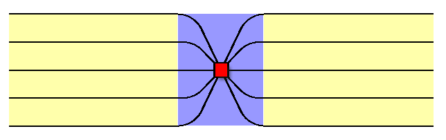
Click on the black lines, which represent the well legs, to select a leg. Click in the yellow area between the legs to select a side. Note: if there are multiple layers, the topmost layer is selected. Click in the purple area between the legs to select the layer. Click in the red area to select the pad.
How do I move a well pad along with its laterals?
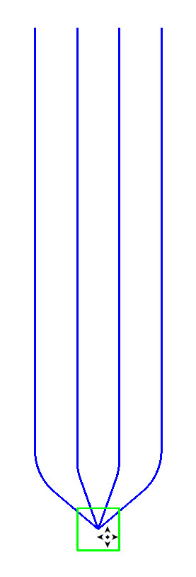 You can move a well pad and its laterals by dragging the platform to a new position while in Edit mode.
-
Select your well pad using one of the methods above.
-
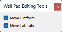
A pop-up dialog will appear with options to move the platform and/or the laterals. To move everything, keep both options toggled on.
-
While in Edit mode(
) , place your cursor on the platform. -
When your cursor changes (
 ), click and drag the well pad to its new position.
 -
Click Stop (
 ) to exit Edit mode.
How do I move a well pad without the laterals?
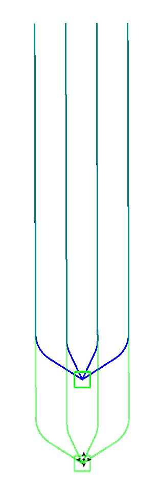
You can move a well pad to a new position but leave the laterals where they are while in Edit mode.
-
Select your well pad using one of the methods above.
-
In the pop-up dialog, only toggle on Move Platform.
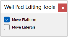
-
While in Edit mode(
) , place your cursor on the platform. -
When your cursor changes (
), click and drag the well pad to its new position. -
Click Stop (
) to exit Edit mode.
How do I move laterals but leave the well pad?
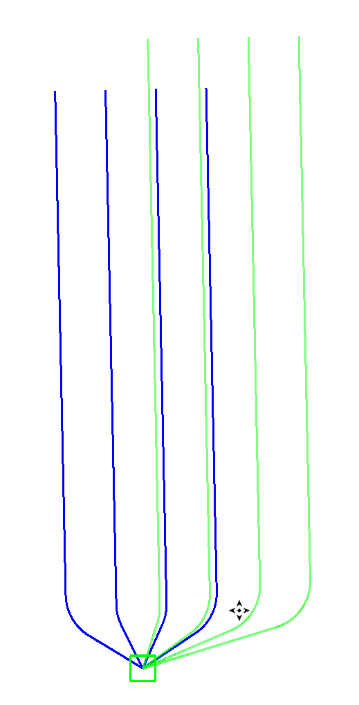 You can move a well pad's laterals to a new position but leave the platform where it is while in Edit mode.
-
Select your well pad using one of the methods above.
-
In the pop-up dialog, only toggle on Move Laterals.
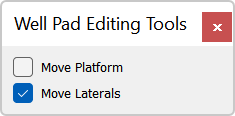
-
While in Edit mode(
) , place your cursor on the platform. -
When your cursor changes (
), click and drag the laterals to its new position. -
Click Stop (
) to exit Edit mode.
How do I rotate the well bores of a well pad for a layer?
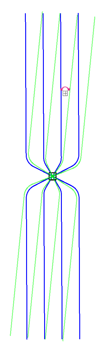 You can rotate all of the well bores in a layer for a well pad by dragging the well bores around the platform while in edit mode. Alternatively, you can use the Azimuth settings in the Object Properties dialog box.
-
Select the well pad layer.
-
While in Edit mode(
), place your cursor on the well bores. -
When your cursor changes (
 ), click and drag the well bores to a new position. You will see an outline of the well bores in the Highlight Color as you move your cursor. Note: You will see that the Azimuth settings will also change in the Object Properties dialog box.
 -
Click Stop (
) to exit Edit mode.
How do I rotate the well bores of a well pad for a side?
You can rotate all of the well bores on one side of the well pad by dragging the well bores around the platform while in edit mode. Alternatively, you can use the Azimuth settings in the Object Properties dialog box. 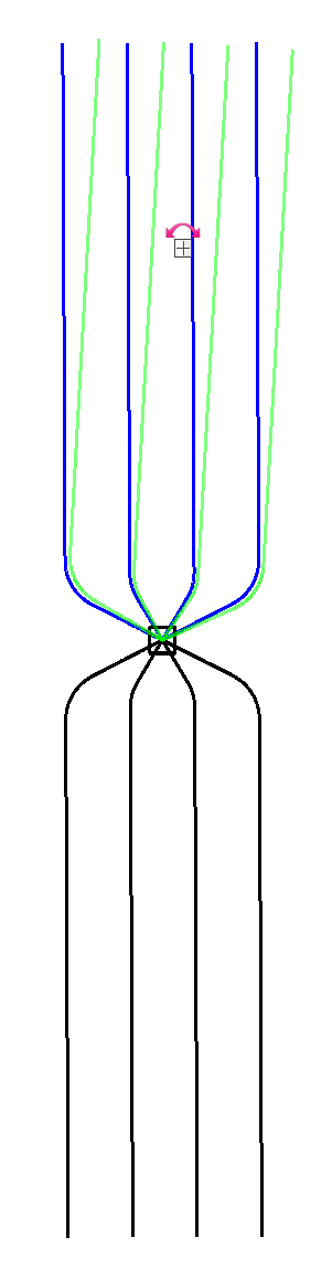
-
Select the well pad side.
- In the pop-up dialog, only toggle on Rotate Side.
-
While in Edit mode(
), place your cursor on the well bores. -
When your cursor changes (
), click and drag the well bores to a new position. You will see an outline of the well bores in the Highlight Color as you move your cursor. Note: You will see that the Azimuth settings will also change in the Object Properties dialog box. -
Click Stop (
) to exit Edit mode.
How do I move the well bores of a well pad for a side?
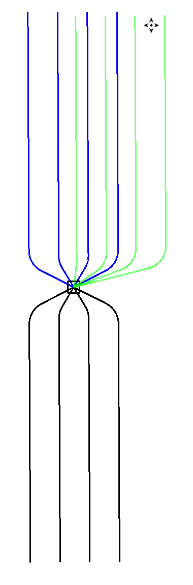 You can move all of the well bores on a side of the well pad by dragging the well bores around the platform while in edit mode.
-
Select the well pad side.
- In the pop-up dialog, only toggle on Move Laterals.
-
While in Edit mode(
), place your cursor on the well bores. -
When your cursor changes (
), click and drag the well bores to a new position. You will see an outline of the well bores in the Highlight Color as you move your cursor. -
Click Stop (
) to exit Edit mode.
Note: The platform does not move when editing this way.
How do I edit the heel and toe point?
You can edit the heel and toe points of individual legs of your well pad while in Edit mode. Be cautious when adjusting the heel point as this may drastically affect the trajectory of the well bore.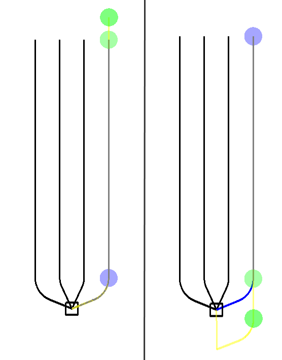
-
Select the leg you want to edit.
-
While in Editmode (
), you will see editing nodes appear at the heel and toe points of the well bore. -
Click on the point you want to edit, and drag the point to a new location. Changes will be reflected immediately in the Statistics dialog box and Pad Plan 3D window.
-
Click Stop (
) to exit Edit mode.
Note: You can not delete heel and toe points.
How do I add additional points along the well bore?
-
Select the leg you want to edit.
-
While in Edit mode (
), you will see the Well Pad Editing Tools dialog box. You will see an editing node appear at the heel and toe point of the well bore, and along the well bore if the option to sample was turned on.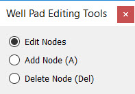
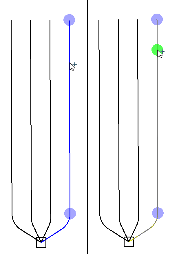
-
Press A on your keyboard. When your cursor changes (
 ), click to add a point. Alternatively, select Add Node in the dialog box and then and then click on the well bore where you want to add a node.
 -
Click and drag to adjust the position of the node.
-
Click Stop (
) to exit Edit mode.
How to I remove points along the well bore?
-
In Edit mode, select the leg you want to edit.
-
Select the node you want to delete. When the node appears in the highlight color press Delete on the keyboard. Alternatively, select Delete Node in the dialog box and then click on the not you want to delete.
The Undo and Redo buttons can be used to undo or redo any changes made.  .
.
Stamped well pads will not revert to the template when edits are made to the well pad in object properties, unless an edited object is completely deleted. To discard all edits, and return to the parameters as defined in Object Properties, click Reset Well Pad under that pad's Object Properties.
— MORE INFORMATION

|
Copyright © 2020 | SeisWare International Inc. | All rights reserved |