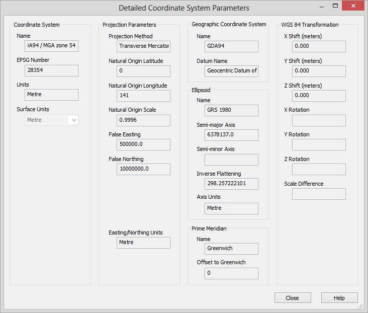
Detailed Coordinate System Parameters
This Detailed Coordinate System Parameters dialog displays detailed information about the currently selected coordinate system.
Coordinate System
This section displays basic information about the coordinate system.
EPSG Number: This is the official EPSG (European Petroleum Survey Group) number defining the coordinate system. Coordinate systems are based on a table of coordinate systems published by the EPSG. Note: If this field is blank it means that this is a custom coordinate system.
Units: These are the default surface units for the selected coordinate system. Note: If the Units are missing this is likely a geographical rather than a projected coordinate system.
Surface Units: The surface units being used for the coordinate system. Typically this will be the same as the Units value, but you can override this selection in the main dialog to work in units other than the predefined coordinate system units.
Projection Parameters
This section displays information detailing how latitude/longitude data is projected onto the map. Note: If there are no parameters in this section this is likely a geographical rather than a projected coordinate system. Use of geographical coordinate systems is not recommended within the software.
Projection Method: The method of projecting
latitude/longitude data onto the map. We support the following
projection methods.
- Albers Equal Area
- First Parallel Latitude
- Second Parallel Latitude
- False Origin Latitude
- False Origin Longitude
- False Origin Easting
- False Origin Northing
- American Polyconic
- Cassini-Soldner
- Hotine Oblique Mercator
- Projection Center Latitude
- Projection Center Longitude
- Initial Line Azimuth
- Rectified to Skew Angle
- Initial Line Scale
- False Easting
- False
Northing
- Lambert Conic Conformal (1SP)
- Lambert Conic Conformal (2SP Belgium)
- False Origin Latitude
- False Origin Longitude
- First Parallel Latitude
- Second Parallel Latitude
- False Origin Easting
- False Origin Northing
- Lambert Conic Conformal (2SP)
- False Origin Latitude
- False Origin Longitude
- First Parallel Latitude
- Second Parallel Latitude
- False Origin Easting
- False Origin Northing
- Mercator (1SP)
- Mercator (2SP)
- New Dixieland Map Grid
- Oblique Mercator
- Projection Center Latitude
- Projection Center Longitude
- Initial Line Azimuth
- Rectified to Skew Angle
- Initial Line Scale
- Projection Center Easting
- Projection Center Northing
- Oblique Stereographic
- Polar Stereographic (variant A)
- Transverse Mercator
- Transverse Mercator (South Orientated)
Projection Parameters
The following is a complete list of possible projection parameters for
various projection methods.
Natural Origin Latitude: The latitude of the
point of the central reference for the coordinate system.
Natural Origin Longitude: The longitude of
the point of the central reference for the
coordinate system. This is often referred to as the central meridian.
Natural Origin Scale: A scale factor applied
to produce the projected grid. This scale factor is defined at the
natural origin.
False Easting: The projected value in the X direction defined at the origin longitude. This is typically a large value such as 500,000 which is used to avoid having to deal with negative projected values.
False Northing: The projected value in the Y direction defined at the origin latitude. This value will typically be zero.
First Parallel Latitude: Used with conic projections, this is he latitude of the one of the parallels that intersects the cone with the ellipsoid.
Second Parallel Latitude: Used with conic projections, this is he latitude of the one of the parallels that intersects the cone with the ellipsoid.
False Origin Latitude: The latitude at the point that the False Origin Easting and False Origin Northing are defined.
False Origin Longitude: The longitude at the point that the False Origin Easting and False Origin Northing are defined.
False Origin Easting: The projected value in the X direction defined at the intersection of the False Origin Latitude and False Origin Longitude.
False Origin Northing: The projected value in the Y direction defined at the intersection of the False Origin Latitude and False Origin Longitude.
Projection Center Latitude: The latitude of the point at which the Initial Line Azimuth is defined.
Projection
Center Longitude: The longitude of the point at which the
Initial Line Azimuth is defined.
Initial Line Azimuth: The angular direction of the center line for an oblique projection.
Rectified to Skew Angle: The angle the projection is rotated to point to true north.
Initial Line Scale: A scale factor applied to produce the projected grid. The scale factor is defined at the intersection of the Projection Center Latitude and Projection Center Longitude.
Projection Center Easting: The projected value in the X direction defined at the intersection of the Projection Center Latitude and Projection Center Longitude.
Projection
Center Northing: The projected value in the Y direction
defined at the
intersection of the Projection Center Latitude and Projection Center
Longitude.
Geographic Coordinate System
This
section displays information about the geographic coordinate system.
The geographic coordinate system is the earth model that represents
locations on the earth in latitudes and longitudes.
Name: The name of the geographic coordinate system. If this is an EPSG coordinate system this will be the EPSG name.
Datum Name: The name of the geodetic
datum for the geographic coordinate
system. The geodetic datum is the reference model of the earth that the
coordinate system is based on. If this is an EPSG coordinate system the
name will be the EPSG name.
Ellipsoid
This section displays information about the ellipsoid of the coordinate system. The ellipsoid is a mathematical model of the shape of the earth that approximates the actual shape of the earth. The ellipsoid is sometimes referred to as the spheroid.
Name: The name of the ellipsoid. If this is an EPSG coordinate system this will be the EPSG name of the ellipsoid.
Semi-major Axis: The semi-major axis is the radius of the earth at the equator used for this ellipsoid. It is defined as one half of the largest diameter of the earth at the equator.
Semi-minor Axis: The semi-minor axis is the radius of the earth through the north and south pole for this ellipsoid. It is defined as one half of the largest diameter of the earth running through the poles. Note: Only one of the parameters Semi-minor Axis and Inverse Flattening are typically defined as one can be derived from the other.
Inverse Flattening: A measure of the flattening of the ellipsoid's poles toward the equator. It is an inverse ratio (1 / f) represented by the flattening formula f = ((a - b) / a) where a is the semi-major axis and b is the semi-minor axis. Note: Only one of the parameters Semi-minor Axis and Inverse Flattening are typically defined as one can be derived from the other.
Axis Units: These are the units of
measure for the semi-major and semi-minor axes. This will typically be
meters.
Prime Meridian
This
section displays information
about the prime meridian of the coordinate system. The prime meridian
is the line of longitude for the coordinate system defined to be zero
degrees.
Name: The name of the prime meridian. If this is an EPSG coordinate system this will be the EPSG name of the prime meridian.
Offset to Greenwich: The offset in
decimal degrees of the prime meridian to the
Greenwich Meridian (also known as the International Meridian). This
parameter is used to convert data between different coordinate systems.
WGS 84 Transformation
This
section displays information
about datum shifts which are applied when converting between different
coordinate systems. A datum shift is the difference between the same
coordinate in two different coordinate systems. Because datum shifts
can vary from place to place within a coordinate system it is common to
specify a custom datum shift that represents the specific area you are
interested in. The datum shift in this dialog is used to specify the
shift that needs to be applied to place a location in the same spot as
in the WGS 84 (World Geodetic System 84) coordinate system. All datum
shifts between different coordinate systems are performed relative to
the reference coordinate system WGS 84. You will specify either the
three X,Y and Z shift parameters or all seven parameters depending on
the datum shift method used.
X Shift: Specifies
the datum shift in the X (typically east/west)
direction needed to transform a point to the equivalent position in the
WGS 84 coordinate system. This shift is always specified in meters.
Y Shift: Specifies the datum shift in
the Y direction (typically north/south) needed to transform a
point to the equivalent position in the WGS 84 coordinate system. This
shift is always specified in meters.
Z Shift: Specifies
the datum shift in the Z (elevation) direction
needed to transform a point to the equivalent position in the WGS 84
coordinate system. This shift is always specified in meters.
X Rotation: Specifies a rotation factor
applied in the X direction. This is specified in seconds of arc.
Y Rotation: Specifies a rotation
factor applied in the Y direction. This is specified in seconds of
arc.
Z Rotation: Specifies a rotation
factor applied in the Z direction. This is specified in seconds of arc.
Scale Difference: Scaling factor applied
to the transformation. The scaling factor is specified in parts per
million.
Also See
— MORE INFORMATION

|
Copyright © 2020 | SeisWare International Inc. | All rights reserved |