Automatic Well Planning
The Automatic Well Planning dialog box is launched from the Well Toolbar using the Multi-Line Automatic Well Planning or Multi-Radial Well Automatic Planning icons. Automatic Well Planning references the working set version of your seismic volume. When you reference a time volume you must have a velocity model and use a time horizon when following a horizon. When you reference a depth volume you must use a depth horizon when following a horizon, but only need to select a velocity model if you want to generate velocity curves for the new wells.
Although the well plan references a specific seismic volume, you can extend the plan past the seismic data. The last time or depth point is used and extended horizontally to the bottom hole location.
After creating a well using the Automatic Well Planning tool, you can view and modify the properties of the well in the Well Properties window, and edit the well plan using the Well Planning tool.
- Click the Multi-Line Automatic Well Planningicon
 or the Multi-Radial Well Automatic Planning icon
  on the Well Toolbar.
 - Specify the Number of Wells you want to create.
- Select a Velocity Model from the list of available models. If this list is empty, you need to create a model using the Velocity Modeling application.
- Select a horizon to follow and enter a Horizon Offset. Use negative values to create the plan above the horizon, and positive values to place the plan below the horizon.
- Enter a UWI for the well. When you are creating multiple plans each well will be assigned the UWI followed by a number, beginning with "1" for the first well.
- Draw the well plan on the Basemap.
- For Multi-Line Plans:
- Click on the top hole location, hold down the mouse button, and then release the mouse at the bottom hole location. You will see a line on the map indicating the placement of the planned well.
- Click and drag your cursor to place additional wells. The first planned well will remain in its original location, and lines representing additional well plans will move with your cursor, placed evenly between the first and last wells.
- Release the mouse button. You will see lines on the map indicating the placement of all of the planned wells.
- For Multi-Radial Plans:
- Click on the top hole location and hold down the mouse button.
- Move your cursor. You will see multiple lines radiating evenly from the top hole location.
- Release the mouse button. You will see lines on the map indicating the placement of all of the planned wells.
- Click
 . The well or wells will be saved to the database, and can be edited from the Well Properties window.
General Information
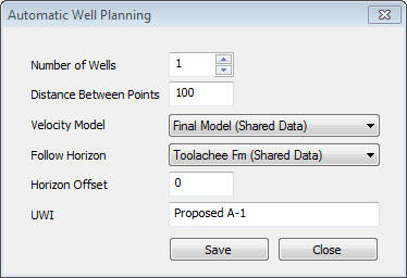
Distance Between Points: Enter the distance in map units that you want between each inflection point on the well plan.
Velocity Model: Select a velocity model from the list of available models. If this list is empty, you need to create a model using the Velocity Modeling application.
Follow Horizon: Select a horizon from the list of horizon. This, along with the velocity model, is used to determine the final depth for the well plan. If the horizon doesn't exist where you are planning your well, you will get an error message. When the working set version of your seismic line is in time, select a time horizon, and when it is in depth, select a depth horizon.
Horizon Offset: Enter a horizon offset value that will be used to determine the final placement of the well plan. Use negative values to create the plan above the horizon, and positive values to place the plan below the horizon. When the working set version of your seismic line is in time, offsets should be in milliseconds, and when the working set version of your seismic line is in depth, the offsets should be in depth units.
UWI: Enter a UWI for the well or wells. When multiple wells are being a planned, a number will be added to the end of each UWI, starting with "1". You can edit the UWI information from the Well Properties windowafter they have been created.
Also See
— MORE INFORMATION

|
Copyright © 2020 | SeisWare International Inc. | All rights reserved |